4
1.00 = Reference source
0.98 = Carbon filed surface
0.98 = Frost crystals
0.98 = Skin human
0.97 = Slate
0.96 = Water distilled
0.96 = Ice smooth
0.95 = Soil saturated with
water
0.95 = Carbon candle soot
0.94 = Glass polished plate
0.94 = Paint, oil
0.93 = Brick red
0.93 = Paper white bond
0.92 = Concrete
0.92 = Soil dry
0.91 = Plaster rough coat
0.90 = Wood planed oak
0.90 = Glazed earthenware
0.89 = Snow, granular
0.88 = Glazed Silica
0.87 = Cuprous Oxide
at 38°C
0.86 = Emery Corundum
0.85 = Snow
0.85 = Stainless oxidized
at 800°C
0.84 = Oxidized Iron
at 500°C
0.83 = Cuprous Oxide
at 260°C
0.82 = Snow, fine particles
0.81 = Brass, unoxidized
0.80 = Glass, convex D
0.79 = Steel oxidized
0.78 = Copper heavily
oxidized
Emissivity Table
0.77 = Cotton cloth
0.76 = Sand
0.75 = Unglazed silica
0.74 = Oxidized iron
at 100°C
0.73 = Coating No. C20A
0.72 = Basalt
0.71 = Graphitized carbon
at 500°C
0.70 = Red Rust
0.69 = Iron sheet heavily
rusted
0.67 = Water
0.66 = Black Loam
0.65 = White cement
0.64 = Iron cast oxidized
0.63 = Lead oxidized
at 1100°F
0.62 = Zirconia on inconel
0.61 = Cu-Zn, brass
oxidized
0.58 = Inconel sheet
at 760°C
0.56 = Smooth white marble
0.55 = Al anodized chromic
acid
0.21 = Iron cast polished
0.20 = Brass rubbed 80
grit emery
0.16 = Stainless steel
18-8 buffed
0.09 = Aluminium as
received
0.07 = Steel polished
0.05 = Aluminium polished
sheet
0.05 = Copper polished
0.03 = Brass highly polished
Infrared (IR) Thermometer
Operating Instructions
#61-685
Instrument - Description
7
8
9
5
6
1
2
3
4
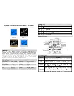
Feature Callouts
1. LCD display
2. Up key
3. Down key
4. Mode key
5. Thermocouple socket
6. Trigger key
7. Infrared lens
8. Class II laser
9. Battery cover
IMPORTANT SAFETY INFORMATION
Read
and
understand
all of the instructions and safety infor-
mation in these operating instructions before using this meter.
Use the meter only as specified in this manual; otherwise, the
protection provided by the meter may be impaired.
A
WARNING
statement identifies hazardous conditions
and actions that could cause bodily harm or death.
WARNINGS
To avoid possible electric shock, personal injury or death follow
these guidelines:
• Do not look directly into the laser beam – permanent eye
damage may result.
• Do not use a thermocouple on a live circuit.
• Do not use if meter appears damaged. Visually inspect the
meter to ensure case is not cracked.
• Do not use meter if it operates abnormally as protection
maybe impaired.
• Do not use without the battery and the battery case properly
installed.
• Do not attempt to repair this unit as it has no user-service
-
able parts.
• Replace battery if erratic operation occurs.
• Verify the thermometer is working properly by taking a
reading on a known measurement.
2
1
11
2
7
8
9
10
3
4
5
6
HOLD
C
F
LOCK
HI
LOW
Operating the Thermometer
To measure temperature, aim the thermometer at an object and
pull the trigger key. Be sure to consider the distance to spot size
ratio. The laser is used for aiming only.
Display
1. °F / °C Symbol -
Fahrenheit / Celsius
2. Hi alarm and low
alarm symbol
3. Low battery symbol
4. Measuring
temperature symbol
5. Lock mode for
continuous reading
6. Backlight “on” symbol
7. Laser “on” symbol
8. Holds and displays last temperature measured
9. Current temperature value
10. Function mode icons for MAX, MIN, DIF, ( ), AVG, HAL,
LAL, PRB, E, E
11. Temperature values for MAX, MIN, DIF, ( ), AVG, HAL,
LAL, PRB and emissivity values for E
Optical Resolution
Ratio of the distance from the measured object vs. the spot size
of the measurement area.
Emissivity
Emissivity is the ratio of infrared energy emitted from an
object versus the infrared energy emitted by a black body.
The emissivity of the perfect black body is 1. All other
materials have an emissivity ratio between 0.1 (highly
reflective) to 1.0 (Ideal black). Emissivity is determined
primarily by the material from which an object is con-
structed and its surface finish.
The thermometer allows emissivity adjustment for the
type of surface being measured. Refer to the following
emissivity table.
1” @ 12”
3” @ 36”
5” @ 60”
Distance
Spot
D 12
=
S 1
3