background image

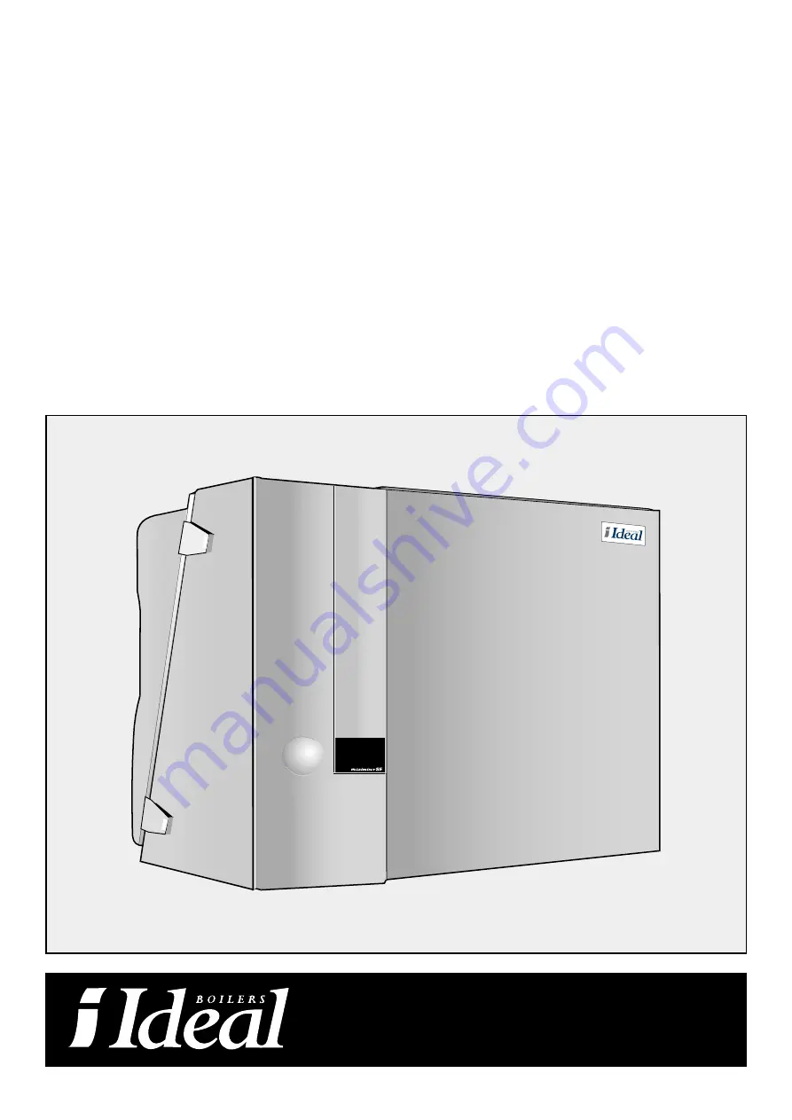
Maximiser SE 42 & SE 65

Installation & Servicing instructions

Wall Mounted, Fanned, Super Efficient Gas Boilers

Natural Gas Models Only
Maximiser SE 42

G.C. Appliance No. 41-349-85

Maximiser SE 65

G.C. Appliance No. 41-349-86

CAUTION. 

To avoid the possibility of injury during the installation, servicing or cleaning of this

appliance care should be taken when handling edges of sheet steel components.

Summary of Contents for Maximiser SE 42

Page 1: ...Gas Boilers Natural Gas Models Only Maximiser SE 42 G C Appliance No 41 349 85 Maximiser SE 65 G C Appliance No 41 349 86 CAUTION To avoid the possibility of injury during the installation servicing or cleaning of this appliance care should be taken when handling edges of sheet steel components ...

Page 2: ......

Page 3: ...laws of the local water authority the building regulations and the Building Standards Scotland and any relevant requi rements of the local authority Detailed recommendations are contained in the following British Standard Codes of Practice BS 6891 Low pressure installation pipes BS 6798 Installation of gas fired hot water boilers of rated input not exceeding 60 kW BS 5449 Forced circulation hot wa...

Page 4: ...r 33 36 ppm 19 21 Water content Lt 3 6 4 7 gal 0 78 1 02 Weight kg 72 75 lb 159 165 IP Rating IP 44 IP 44 Power Consumption W 180 180 Seasonal efficiency SEDBUK 90 4 90 5 The manufacturer s notes must NOT be taken in any way as overriding statutory obligations IMPORTANT These appliances are CE certificated for safety and performance It is therefore important that no external control devices e g fl...

Page 5: ...he boiler is to be fitted in a timber framed building it should be fitted in accordance with the Institute of Gas Engineers document IGE UP 7 2 BOILER CLEARANCES The following minimum clearances must be maintained for operation and servicing Front of boiler 450 mm Sides of boiler 50 mm Above boiler dependant upon the system Below boiler 100 mm 685 55 130 656 731 335 900 110 158 450 46 30 450 152 3...

Page 6: ...ty 1 General a The installation must comply with the requirements of BS 6798 and BS 5449 b The installation should be designed to work with flow temperatures of up to 90 C and a temperature differential of 20 C c All components of the system including the heat exchanger of the indirect cylinder must be suitable for a working pressure of 3 bar 45 Lbf in2 and temperature of 110 C Care should be take...

Page 7: ...ecommended and MUST NOT be used on sealed systems The appliances are NOT suitable for gravity central heating nor are they suitable for the provision of gravity domestic hot water The hot water cylinder and ancillary pipework not forming part of the useful heating surface should be lagged to prevent heat loss and any possible freezing particularly where pipes run through roof spaces and ventilated...

Page 8: ...iew 1 Frame 2 Heat exchanger 3 Ionisation probe 4 Lower access cover 5 Safety sensor 6 Sight glass 7 Temperature pressure gauge 8 Display 9 Igniter 10 Control panel 11 Gas inlet pipe 1 2 to valve 12 Condensate drain 32 mm 13 Burner 14 Flow connection 15 Return connection 16 Burner thermostat 17 Gas injector 18 Hand held diagnostic 19 Electrical terminal connection options 20 Fan 21 Air gas connect...

Page 9: ...raphs for more information about connecting the central heating gas and flue gas discharge pipes and the condensate drain 9 VENTILATION Safe efficient and trouble free operation of open flued gas boilers is vitally dependent on the provision of an adequate supply of fresh air to the room in which the appliance is installed Ventilation by grilles communicating directly with the outside air is requi...

Page 10: ...t building through ventilators windows doors other sources of natural air infiltration or forced ventilation air conditioning If this should occur the appliance MUST be turned OFF labelled as unsafe and corrective action taken TERMINAL POSITION Where the lowest part of the terminal is fitted less then 2 m 80 above a balcony above ground or above a flat roof to which people have access then the ter...

Page 11: ... 7 Concentric Flue Adaptor Supplied within wall roof kits Fig 11 8 Twin Pipe Adaptor 152403 N A Fig 11 9 1 m Extension kit 152400 152401 Not Shown Increaser 80 100 152404 N A Not Shown Air inlet grille 152402 N A The Vertical and Horizontal flue kits are supplied with all the necessary components to allow the connection of the concentric flue system from the boiler to the outside atmosphere The ki...

Page 12: ...º bend Ø 100 mm 0 7 1 6 90º bend Ø 80 125 mm 6 0 45º bend Ø 110 mm 0 2 0 5 90º bend Ø 100 150 mm 2 7 4 5 Straight pipe Ø 80 125 mm per m 4 0 90º bend Ø 80 mm 7 2 16 0 Straight pipe Ø 100 150 mm per m 1 8 3 6 90º bend Ø 90 mm 5 4 12 5 90º bend Ø 100 mm 2 2 4 4 Flue gas discharge system 90º bend Ø 110 mm 0 3 0 6 45º bend Ø 80 mm 3 7 8 9 45º bend Ø 90 mm 2 8 6 7 Straight pipe Ø 80 mm per m 1 5 3 6 45...

Page 13: ... right 2300mm left 2000mm rear 2300mm Note lengths are from side back of boiler Part No Resistance Pa SE 42 SE 65 Flue diameter 80 125 80 125 80 125 Twin pipe adaptor 152403 n a n a Air inlet grille 152402 5 5 6m of 80mm pipe n a 13 2 31 8 approximate length 6000mm Note Flue system supplied by proprietary flue manufacturers This flue design layout would be used where greater flue travel is require...

Page 14: ...No Resistance Pa SE 42 SE 65 Flue diameter 80 125 100 150 80 125 100 150 100 150 Standard flue 152394 152395 34 34 37 2 Extension packs 152400 152401 8 3 6 7 2 2 x 45 elbows 152618 152619 7 4 3 6 5 4 approximate length 3500mm Standard flue 152394 152395 34 34 37 3 x Extension packs 152400 152401 12 5 4 10 8 2 x 45 elbows 152618 152619 7 4 3 6 5 4 approximate length 4500mm Part No Resistance Pa SE ...

Page 15: ...rners 25 mm 1 in 8 From a surface facing the terminal 600 mm 24 in 9 From a terminal facing the terminal 1200 mm 48 in 10 From an opening in the car port eg door window into dwelling 1200 mm 48 in 11 Vertically from a terminal on the same wall 1500 mm 60 in 12 Horizontally from a terminal on the same wall 300 mm 12 in roof terminal positions 13 Directly below an opening air brick windows etc 300 m...

Page 16: ... or additional information on multiple arrangements contact Caradon Ideal Ltd KEY 1 Non return Valve 2 Relief Valve 3 Service Valve 4 Expansion Vessel 5 Mixing Header 6 Flow Sensor 7 System pump 8 By pass 9 Flow control 10 Outdoor Sensor 11 MBC 5 12 Flue gas Terminal 459140 499004 15 Maximiser SE Installation 1 2 3 3 3 4 5 6 7 8 KEY 1 2 boiler basic frame 2 additional single frame 3 support foot 4...

Page 17: ...and the return pipe at about 6 meters distance from the unit The pipe diameter has to be at least 22 mm for an installed capacity of 22 and 30 kW and 28 mm for an installed capacity of 42 kW or over Refer to Fig 17 2 The Ideal Maximiser is not suited for installations with a natural water circulation gravity installations Important information Corrosion in the central heating system depends on the...

Page 18: ... A 20 EXTERNAL WIRING External wiring MUST be in accordance with the current l E E Wiring Regulations The wiring diagrams illustrated in Frames 22 to 23 cover the systems most likely to be used with this appliance For wiring external controls to the boiler reference should be made to the systems wiring diagram supplied by the relevant manufacturer in conjunction with the wiring diagrams shown in F...

Page 19: ...7 18 19 10 12 13 14 15 11 4 3 5 6 7 8 9 1 2 H 16 17 18 10 12 13 14 15 11 4 3 5 6 7 8 9 1 2 yellow blue pink pink black yellow purple blue brown pink purple red green black white red white black white grey white blue white pink purple white black red black white pink brown red red blue red grey red yellow red green red F Safety sensor G Supply sensor H Boiler identification module I ignition gas va...

Page 20: ...cks i e earth continuity polarity resistance to earth and short circuit using a suitable test meter B Gas Installation 1 The whole of the gas installation including the meter should be inspected and tested for soundness an purged in accordance with the recommendations of BS 6891 2 Purge air from the gas installation by loosening the gas cock union and purge until gas is smelt 3 Retighten the union...

Page 21: ...rried out on the boiler These adjustable potentiometers are located behind the control panel cover Adjustment of these meters to the desired value will be dependant upon the type of installation Supply temperature Hot water storage temperature Partial load Test switch 1 Supply temperature Using the upper trimming potentiometer indicated with a radiator to adjust the central heating water temperatu...

Page 22: ...grammer and all other system controls should be proved Operate each control separately and check that the main burner or circulating pump as the case may be responds 2 Water circulation system a With the system HOT examine all water connections for soundness b With the system still HOT turn off the gas water and electricity supplies to the boiler and drain down to complete the flushing process c R...

Page 23: ...suring the differential pressure The differential pressure should be 5 Pa 0 05 mbar with a tolerance of 5 Pa 0 05 mbar Because of this the measured value should be between 10 and 0 Pa The differential pressure can be corrected by turning the adjustment screw of the gas pressure on the gas valve By turning it to the right the differential pressure will decrease Note The adjustment screw is protecte...

Page 24: ... and that the flue system is sealed correctly h If the appliance has been installed in a compartment check that the ventilation areas are clear The servicing procedures are covered more fully in Frames 33 and 34 and MUST be carried out in sequence Note In order to carry out either servicing or replacement of components the boiler casing must removed Refer to frame 8 IMPORTANT After completing the ...

Page 25: ... and inspect the heat exchanger refer to Fig 32 3 If the heat exchanger is polluted major maintenance should be carried out Note The lower access cover plate has to be cleaned with a steel brush before remounting it If the seal is dirty it should be cleaned with a cloth or a soft brush The servicing procedures are covered more fully in Frames 33 to 34 and MUST be carried out in sequence WARNING Al...

Page 26: ...ed with 120 V AC The mains supply MUST therefore always be isolated before removing the burner dangerous voltage above 50 V AC 5 After cleaning the burner the silicone burner sealing gasket can be re used provided it shows no damage If it is damaged it should be replaced Reassemble the burner in reverse order 6 Remove the fan by loosening it from the lower access cover plate refer to Fig 33 3 Insp...

Page 27: ...h 4 lnspect the heat exchanger 4a Remove the lower access cover plate by detaching the quick acting closures at the foot of the heat exchanger refer to Fig 34 1 Subsequently clean the cover plate with a steel brush Clean the gasket with a cloth or a soft brush Remove and check the ionisation electrode Fig 34 2 the igniter Fig 34 4 Note the igniter is very fragile the guide plate Fig 34 3 Never tou...

Page 28: ...replacement 2 Swing the control panel away from the fan 3 Unplug the two electrical connectors from the front of the fan by squeezing the retainers and pulling forwards 4 If fitted remove the retaining block from the top fitting point of the fan 5 Remove the air hose to the heat exchanger by pushing it upward to clear the fan body 6 Pull fan assembly forwards to clear the rear location points lowe...

Page 29: ...assembly and reassemble in reverse order 5 Check the operation of the boiler Lower Access Cover Seal refer to fig 43 3 key 28 1 Follow steps 1 7 of Fan replacement 2 Disconnect siphon from lower access cover plate see fig 33 4 3 Spring open the upper and lower retaining clips of the lower access cover plate and pull downwards to remove 4 Remove the damaged seal from the groove in the cover plate a...

Page 30: ...e UBA 4000 Max safety time 10 sec 220 240 Vac 50 Hz DIN DVGW nr 93 01bNF S CE REG NR 63 A05280 1 2 pump service display reset 211077 35 replacement of components REFER TO FRAME 43 CONT Heat Exchanger refer to fig 43 3 key 19 1 Disconnect the electricity supply 2 Where possible isolate the boiler from the heating system 3 Drain the system water from the heat exchanger 4 Isolate the gas supply at th...

Page 31: ...appear if the unit adjusts itself to the small amount of water in the installation H Unit is in operation for hot water 39 FAULT DIAGNOSIS By combining the display and service codes that are shown with the unit and or installation behaviour the cause of the malfunction can be found Normally the operating code is indicated on the display By pressing the Service button the service code will appear I...

Page 32: ...on is not sufficiency heated The central heating water temperature is higher than the set value Unit in anti fast cycle time Connection for flue gas thermostat not closed Safety sensor of the heat exchanger is overheated The difference in heat between the safety sensor and the supply sensor is too large or the supply and return sensor have been interchanged Temperature of safety sensor is rising t...

Page 33: ...9 37 39 39 39 39 37 39 39 39 40 41 FAULT FINDING CAUSES Cause No Cause description Malfunction causes and remedies The table shown below gives the possible cause of the malfunction described in frame 40 The table also provides instructions of how to remedy the malfunction The room thermostat is not properly connected ensure a proper connection of the poles The room thermostat does not switch off D...

Page 34: ...set When the same fault remains short circuiting in the cable loom has occurred or the control panel is defect otherwise the sensor is defect Sensor defect or improper contacts and connections The connecting wires of the igniter do not make contact or the igniter is defective or the fuse F1 is defective Control panel should supply 120 V to connector Improper gas air ratio Check the air restriction...

Page 35: ...nce of this appliance The full list is held by Caradon Ideal distributors and merchants When ordering spares please quote 1 Boiler model 2 Description 3 Quantity FAULT FINDING Maximiser SE Installation 34 Key No 7 6 1 3 4 5 41 89 72 73 52 56 50 99 104 35 36 25 39 28 30 63 105 G C No E58 940 E58 942 E58 941 E58 954 E58 952 E58 956 E58 962 E58 993 E58 998 E59 737 E59 000 E59 705 E59 005 E59 008 E59 ...

Page 36: ...43 Casing Control panel 43 Heat exchanger 35 Maximiser SE Installation 7 6 1 5 4 3 30 25 28 35 36 41 99 39 21 19 22 31 fig 43 1 fig 43 2 fig 43 5 fig 43 4 fig 43 3 105 104 ...

Page 37: ...43 Fan Gas control 43 Pump Burner Maximiser SE Installation 36 63 72 73 52 53 89 49 56 50 fig 43 6 fig 43 7 57 59 fig 43 8 fig 43 9 ...

Page 38: ......

Page 39: ......

Page 40: ...g Solutions Technical Training Centre offers a series of first class training courses for domestic commercial and industrial heating installers engineers and system specifiers For details of courses please ring Technical Training 01482 498432 Caradon Plumbing Solutions pursues a policy of continuing improvement in the design and performance of its products The right is therefore reserved to vary s...

Reviews: