THE
POWER
OF
RELIABILITY
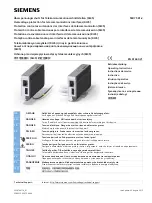
INNOVATIVE CIRCUIT TECHNOLOGY LTD.
855-313-002
ICT DC DISTRIBUTION PANEL
LED
FUSE STATUS
ON
Blown or missing
OFF
Good
INSTRUCTION MANUAL
ICT180S-12 STANDARD MODEL
(SERIES 2)
INSTALLATION
1. Inspect panel and accessories to make sure everything is
complete and in good condition.
2. For rack set up, install panel on the rack using appropriate size
screws and star washers on all four mounting holes. If equipment
rack is not electrically connected to Earth ground, connect a ground
cable from the ground stud on the back of the panel to a known
Earth ground point. Otherwise, the four mounting screws and
washers are sufficient for earth ground connection.
OR
For non-rack set up, connect a ground cable from the ground stud
on the back of the panel to a known Earth ground point.
3. Remove the plastic shield(s) covering the output terminal
block(s) located on the back of the panel. Connect the positive of
the load to the positive terminal point (labeled “+”) and the
negative of the load to the negative terminal point (labeled “-“).
Table 1. Fuse Status LED
Table 2. Form “C” Alarm
4. Install fuse on the front of the panel for each output terminal block.
The fuse number on the front of the panel matches the output
terminal block number on the back of the panel. Use fuse size that
is
a few amps higher than the intended load. For terminal blocks with
no load connected, insert any size fuse to prevent the LED on the front
of the panel from turning on and the alarm from activating if the form
“C” alarm is used.
5. Remove the plastic caps covering the input insulated studs.
Connect the positive of the power source to the red insulated stud
(labeled “+”) and the negative of the power source to the black
insulated stud (labeled “-“).
6. Re-install plastic shield(s) to the output terminal block(s) and
plastic caps to the input studs.
7. For form “C” alarm monitoring, connect your external alarm circuit
to the alarm connector located on the back of the panel. Depending
on your alarm circuit (refer to table 2), you can connect it between
normally open (NO) and common (C), normally close (NC) and
common (C), or both. The alarm connector can be disconnected from
the panel for easy installation.
8. Power up the distribution panel, and check for proper operation of
the connected load(s), fuse status LEDs and form “C” alarm (if using).
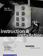
FRONT PANEL
1. FUSE STATUS LEDS: Turns on when a fuse is blown or missing.
2. ATO/ATC FUSES: Location of the ATO/ATC fuses up to 25A.
3. JCASE FUSES: Location of the JCASE fuses up to 40A.
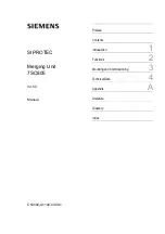
BACK PANEL
1. NEGATIVE INPUT STUD: For DC power source connection up to
180A peak and 150A continuous.
2. OUTPUT TERMINAL BLOCK 10 – 12: For DC load connection up
to 40A each pair.
3. ALARM CONNECTOR: For external alarm circuit to monitor unit
fault.
4. CHASSIS GROUND STUD: For Earth ground connection.
5. OUTPUT TERMINAL BLOCK 1 - 9: For DC load connection up to
25A each pair.
6. POSITIVE INPUT STUD: For DC power source connection up to
180A peak and 150A continuous.
NC/C PINS
NO/C PINS
CONDITION
Open
Closed
One or more blown or missing fuse
All fuses are good and inserted
Closed
Open
No power to unit