ICP WS-855A, User Manual
The ICP WS-855A is a cutting-edge electric shaver designed for precision grooming. Ensure optimum performance with the free User Manual available for download from manualshive.com. This detailed manual provides step-by-step instructions for maximizing the capabilities of your shaver, making grooming a breeze. Experience the ultimate grooming solution today.
Share
Download


Reviews:
No comments
Related manuals for WS-855A

MultiSync X462S
Brand: NEC Pages: 2

P42XC10 - PlasmaSync - 42" Plasma Panel
Brand: NEC Pages: 2

931C - SyncMaster - 19" LCD Monitor
Brand: Samsung Pages: 67

930ND - 64 MB RAM
Brand: Samsung Pages: 86

920NW - SyncMaster - 19" LCD Monitor
Brand: Samsung Pages: 46

916V - SyncMaster - 19" LCD Monitor
Brand: Samsung Pages: 60

913V - SyncMaster - 19" LCD Monitor
Brand: Samsung Pages: 60

910MP - SyncMaster 19" LCD Monitor
Brand: Samsung Pages: 51

931C - SyncMaster - 19" LCD Monitor
Brand: Samsung Pages: 4

940MW - SyncMaster - 19" LCD Monitor
Brand: Samsung Pages: 8
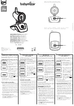
Yoo-Travel
Brand: babymoov Pages: 2
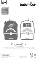
Premium Care
Brand: babymoov Pages: 40

TH-65PF20ER
Brand: Panasonic Pages: 24

Viera TH-42PHD5
Brand: Panasonic Pages: 40

Toughbook CF-VDW07
Brand: Panasonic Pages: 80

SyncMaster S23A550H
Brand: Samsung Pages: 61

U32R590
Brand: Samsung Pages: 44

752174
Brand: Sygonix Pages: 8


