


2 SETTING UP THE IP1000C SYSTEM
1. BEFORE USING THE VE-PG4
2. SETTING UP THE TRANSCEIVERS
INSTALLATION GUIDE
RoIP GATEWAY
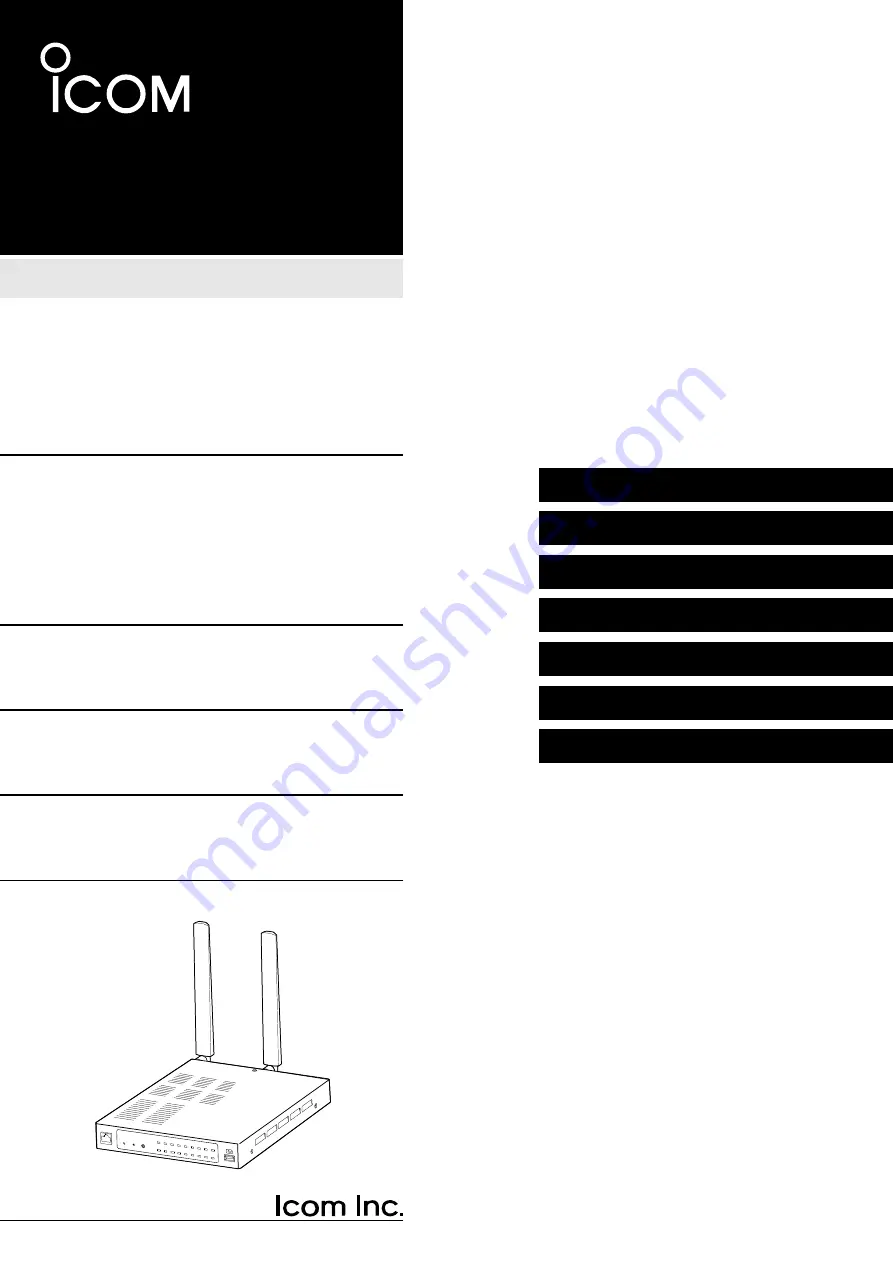
VE-PG4
The Icom VE-PG4 is a versatile communication gateway offering seamless integration for multiple communication systems. Easily set up and configure the device with the Installation Manual available for free download on manualshive.com. Access the manual to get started with your VE-PG4 and enhance your communication capabilities.
2 SETTING UP THE IP1000C SYSTEM
1. BEFORE USING THE VE-PG4
2. SETTING UP THE TRANSCEIVERS
INSTALLATION GUIDE
RoIP GATEWAY
VE-PG4


