background image


1


5000XHV


-


U

NINTERRUPTIBLE 

P

OWER 

S

UPPLY 

-


Q

UICK 

I

NSTALLATION 

G

UIDE


46M5391 

 1:  O

VERVIEW


A

TTENTION

:


Read the Safety Instructions before installing the uninterruptible power supply.  


The uninterruptible power supply and battery modules are heavy. Select a location sturdy enough to handle the weight. 


Refer to the 

Uninterruptible Power Supply Operation and Setup Guide

 for information on how to obtain service and support for the  

unit. 

N

OTE

:


Illustrations in this document might vary in appearance from the purchased unit.


Utility knife or scissors 


Two Phillips screwdrivers (#1 and #2) 


One wrench (10mm) 


Cage nut insertion tool or flat-blade screwdriver (for installing cage nuts in some rack cabinets) 
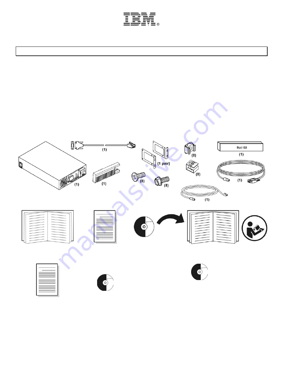
Inventory 


Quick Installation Guide 


Important Notices Flyer 


Documentation 


Warranty Flyer 


PowerChute


Business Edition 
software CD 


Network Management Card documentation CD 


Summary of Contents for 5000XHV

Page 1: ...Supply Operation and Setup Guide for information on how to obtain service and support for the unit NOTE Illustrations in this document might vary in appearance from the purchased unit Utility knife or scissors Two Phillips screwdrivers 1 and 2 One wrench 10mm Cage nut insertion tool or flat blade screwdriver for installing cage nuts in some rack cabinets Inventory Quick Installation Guide Importan...

Page 2: ... Ensure that the outlet supplies proper voltage and phase rotation according to the system rating plate Connect any equipment that will be attached to this product to properly wired outlets When possible use one hand only to connect or disconnect signal cables Never turn on any equipment when there is evidence of fire water or structural damage Disconnect the attached power cords telecommunication...

Page 3: ...emoving the UPS from the shipping carton or installing or removing the UPS in the rack D007 CAUTION Energy hazard present Shorting might result in system outage and possible physical injury Remove all metallic jewelry before servicing C001 CAUTION Lead acid batteries can present a risk of electrical burn from high short circuit current Avoid battery contact with metal materials remove watches ring...

Page 4: ... uninterruptible power supply Y Refer to the instruction sheet included in the rail kit for rail installation details Refer to the diagram below for cage nut clip nut installation The solid squares indicate the cage nut clip nut locations Install the uninterruptible power supply at the bottom of the rack Note Leave 3 U of space below the uninterruptible power supply for each battery pack to be ins...

Page 5: ...sical injury Remove all metallic jewelry before servicing C001 X Open the battery compartment door Y Install the battery modules Z Connect the battery modules Close the battery compartment door Be sure the battery cables are positioned so that they are not pinched Secure the battery compartment door using the screws removed previously Attach the bezel ...

Page 6: ...zed from a remote location without switching to battery operation See Emergency Power Off EPO Option Network Management Card The Network Management Card NMC is factory installed in the uninterruptible power supply Link RX TX 10 100 LED Refer to the NMC documentation for details Status LED Refer to the NMC documentation for details Reset on the NMC Resets the NMC while the unit is connected to util...

Page 7: ...fications for uninterruptible power supply or system events Limits SNMP traps and e mail notifications based on the severity level of the events Provides tools to configure one or more Network Management Cards over the network Provides enhanced security To configure the pre installed Network Management Card of your uninterruptible power supply using this network interface option refer to Chapter 3...

Page 8: ... Management Cards 1 If autorun is enabled the user interface of the CD starts when you insert the APC Network Management Card Utility CD into a computer on your network Otherwise open the file contents htm on the CD 2 Select the Device IP Configuration Wizard from the main menu 3 When the Wizard discovers the unconfigured Network Management Card follow the on screen instructions Note If you leave ...

Page 9: ...Management Card A User Class Identifier by default the identification of the application firmware installed on the Network Management Card 2 A properly configured DHCP server responds with a DHCP offer that includes all the settings that the Network Management Card needs for network communication The DHCP offer also includes the Vendor Specific Information option DHCP option 43 By default the Netw...

Page 10: ... defined by the ARP command For the IP address defined in step 1 use one of the following commands Windows command format ping 156 205 14 141 l 113 LINUX command format ping 156 205 14 141 s 113 3 Use Telnet to access the Network Management Card at its newly assigned IP address For example telnet 156 205 14 141 4 Use apc for both user name and password See Command line interface on page 10 to fini...

Page 11: ... name if configured 3 Enter the User Name and Password apc by default For SNMP use a MIB Browser and the supplied MIB to monitor and configure the Network Management Card of the uninterruptible power supply through SNMP When using high security access disable SNMP Note For more information about how to use any of these interfaces and about how to configure high security access see the User s Guide...

Page 12: ...BE package the user can install just the Agent component for a simpler monitoring system INSTALLING POWERCHUTE BUSINESS EDITION The user can install all three PCBE components on the same computer or on different computers on the network The PCBE Agent component however must be installed on a computer that is connected to an uninterruptible power supply with the supplied serial cable For Windows Op...

Page 13: ...ssible to install PCBE Agents after the initial installation These Agents can be added to the device list of any PCBE Server that uses the same password and user name Follow these steps 1 Use PCBE Console to log on to the PCBE Server 2 Select Configure Device List from the Tools menu 3 Highlight a PCBE Agent to be added in the Discovered Devices list and click Add 4 Repeat step 3 for each PCBE Age...

Page 14: ...gs are 9 bits per second 9600 9 data bits 8 9 parity none 9 stop bit 1 9 flow control none c Click Enter 5 Once the blank terminal window is open follow these steps to configure the output voltage a Press Enter to initiate terminal mode b Press 1 to select uninterruptible power supply Settings Wait for the uninterruptible power supply Settings menu to appear on the screen c Press 1 to select Outpu...

Reviews: