


Welcome. . .
Thank you for buying an
IBM xSeries server.
This server
contains information for setting
up and configuring your server.
For detailed information
about your server, view the
on the
You can also find the most
current information about your
server on the IBM Web site at:
http://www.ibm.com/support/
Installation Guide
User's Guide
Documentation CD.
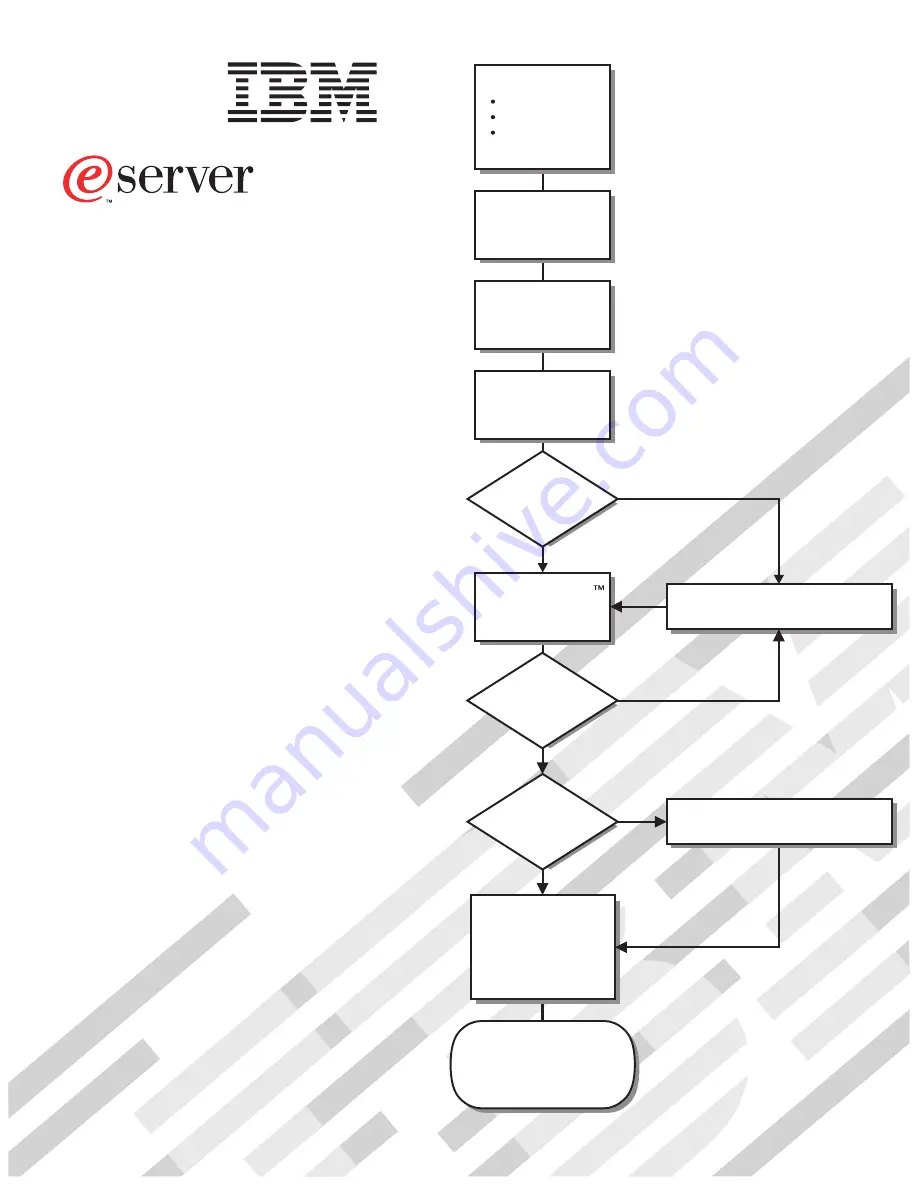
Go to the Server Support
flow chart inside this cover page.
Cable the server
and options
Start the server
Install options:
Drives
Adapters
Memory
Did the server
start correctly?
Yes
No
Use ServerGuide
to set up and
configure hardware
Did configuration
complete?
Use
ServerGuide to
install operating
system?
Use ServerGuide to
install applications,
such as IBM systems
management software
and IBM ServeRAID
programs
System is ready to use.
Go to the Server Support
flow chart to register
your server.
Go to the Web for Instructions,
http://www.ibm.com/support/
No
Yes
Yes
No
Installation Guide
Install the server in
the rack, if required
xSeries 206m
Types 8485 and 8490
Summary of Contents for 206m - eServer xSeries - 8485
Page 3: ...xSeries 206m Types 8485 and 8490 Installation Guide ...
Page 52: ...38 xSeries 206m Types 8485 and 8490 Installation Guide ...
Page 62: ...48 xSeries 206m Types 8485 and 8490 Installation Guide ...
Page 108: ...94 xSeries 206m Types 8485 and 8490 Installation Guide ...
Page 109: ......
Page 110: ... Part Number 40K2367 Printed in USA 1P P N 40K2367 ...


