background image

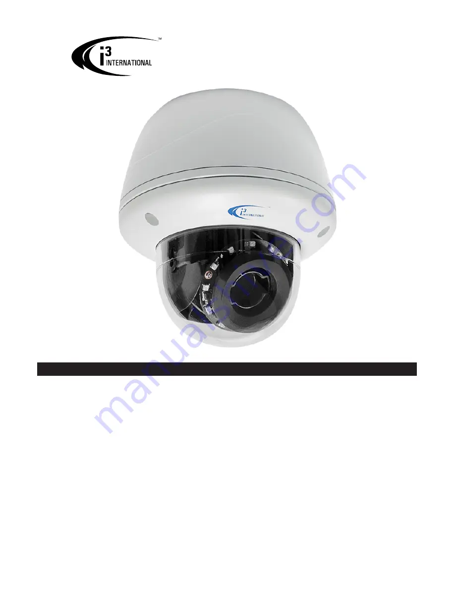
Ax45RM/65RM-series

User Manual

Before attempting to connect or operate this product, read these instructions carefully.
Save this manual for future use. 

CONTENTS

1.  Warnings and operation notes..................................3
2.   Unpacking................................................................5
3.  Dimensions & Parts Identification...........................6
4.   Installation...............................................................7
5.  Connecting to the SRX-Pro Server.........................16
6.  Advanced Camera Setup.........................................21
7. Specifications.....................................................

54

Summary of Contents for Ax45RM series

Page 1: ...this product read these instructions carefully Save this manual for future use CONTENTS 1 Warnings and operation notes 3 2 Unpacking 5 3 Dimensions Parts Identification 6 4 Installation 7 5 Connecting to the SRX Pro Server 16 6 Advanced Camera Setup 21 7 Specifications 54 ...

Page 2: ...or any particular purpose Neither i3 International Inc nor its dealers or distributors shall be liable to any person or entity with respect to any liability loss or damage caused or alleged to have been caused directly or indirectly by this information Furthermore i3 International Inc reserves the right to revise this publication and to make changes to the content at any time without notice FCC Th...

Page 3: ...pose the product to rain or moisture Camera s default IP address is 192 0 0 16 Camera s default Subnet mask address is 255 255 255 0 Default camera User Name i3admin and default Password i3admin 1 1 Precautions Installation and servicing should be performed only by qualified and experienced technicians to conform to all local codes and to maintain your warranty When installing your Ax45RM 65RM cam...

Page 4: ...void electrical shock and to preserve the product warranty DO NOT disassemble the camera Refer servicing to qualified personnel only 1 5 Routine Maintenance The dome bubble is an optical part Use a soft and dry cloth to remove any fingerprints and dust Clean the camera housing with a soft and dry cloth For more stubborn marks use a cloth dampened with a small quantity of neutral detergent then wip...

Page 5: ...e Mount Template 3 Security torx bit x1 4 Flush Mount template x1 5 Round Head Screw Tapping Type with O ring x4 6 Plastic Anchor x4 7 3 ft netowrk cable x1 8 Long Machine Type screws x3 for flush mounting with back box installations 9 Standard Rj45 connector x2 Note Based on installation location and surface type supplied screws and anchors may not be adequate Mounting hardware is site specific a...

Page 6: ...indoor and outdoor installation in commercial and residential environment With 3 axis mount support it provides flexible installation on a ceiling or wall even on an angle The dome camera is a fully integrated enclosure with a back box camera and lens 9 10 11 147 mm 5 68 mm 2 67 94 mm 3 7 158 mm 6 63 mm 2 5 84 mm 3 3 63 mm 2 5 1 2 5 3 4 6 7 8 ...

Page 7: ...oSD Card slot for on camera edge video storage microSD cards up to 64GB supported not supplied 14 Mini USB port Manufacturer use only 15 Screws attaching camera module to the back box x3 silver 16 Screws to engage locking arms x2 black 4 Installation Ax45RM 65RM camera series can be flush wall surface or T bar ceiling mounted without additional mounting accessories brackets Start by marking out an...

Page 8: ...dule 6 Do not completely remove the screws from the dome bubble Set the dome bubble aside 2 Use Phillips screwdriver to loosen three silver screws attaching camera to the back box 15 3 Remove camera s back box and set aside 4 2 I O Connectors Reserved for future use Once the camera s back box has been removed Ax45RM Ax65RM input output connectors will be revealed on the camera s module including R...

Page 9: ... GND COM 4 3 3 Axis lens position adjustment Pan Adjustment Rotate the lens base max 354 until satisfied with the field of view Note Over rotation past 354 will cause internal cables to become damaged disconnected or twisted Horizontal Rotation Firmly grasp the camera lens assembly and rotate counter clockwise clockwise max 354 until satisfied with the field of view Note Over rotation past 354 wil...

Page 10: ...e the back box The Long Machine Type screws provided are used to secure the camera to the back box through ceiling Important Please Read It is the installer s responsibility to ensure that the mounting surface is suitable for the chosen installation method Based on installation location and surface type supplied screws and anchors may not be adequate Mounting hardware is site specific and may need...

Page 11: ...s on the camera module clockwise to Locking arms x2 engage the locking arms Tighten the arms securely against the mounting surface 8 Adjust the lens angle by rotating and panning the camera lens base Lift off the camera liner for easy lens position adjustment Do not over rotate the camera lens beyond the stop point to avoid damage to the camera 9 Once the desired view is achieved replace camera li...

Page 12: ...ur installation environment insert supplied screw anchors into the holes on the mounting Lens Direction GUIDE PATTERN surface 4 Based on installation requirements you may route the cable through the camera s side conduit opening on the back box In that case no additional openings are required in the mounting surface Alternatively drill a 3 4 circular opening in the mounting surface corresponding t...

Page 13: ... and connect to the camera including RJ45 PoE Network cable AC 24V cable if using alarm and audio cables if using Do not apply power until the installation is complete 12 Re attach the camera to the mounted back box Use a Phillips screwdriver to re tighten three silver screws attaching camera to the back box 13 Adjust the lens angle by rotating and panning the camera lens base Lift off the camera ...

Page 14: ...hardware and instructions supplied with the goose neck bracket 2 For Pole Mount installations Use a 3 4 Electrical EMT Conduit Fitting with a rigid 3 4 pipe for this type of installation 3 For both DB60 Wall Mount and Pendant Pole Mount installations camera cabling is to be routed through the camera s top conduit Disassemble the Camera 4 Disassemble the camera by removing the dome bubble Use the p...

Page 15: ... attaching camera to the back box 11 Adjust the lens angle by rotating and panning the camera lens base Lift off the camera liner for easy lens position adjustment Do not over rotate the camera lens beyond the stop point to avoid damage to the camera 12 Once the desired view is achieved replace camera liner until it snaps back into place Complete the Installation 13 Replace the camera s dome bubbl...

Page 16: ...ernet Explorer Version 10 0 or later or latest available Firefox CPU Intel Pentium Core 2 or higher Memory 1GB or more VGA card supporting Direct X 9 0 or above Power Supply Your camera requires PoE power supply Use a RJ45 network connector to connect the camera to your computer or hub switch Note Camera damages resulted from improper power application are NOT covered by the camera warranty Switch...

Page 17: ...ctiveX controls Enable Download signed ActiveX controls Prompt recommended Download unsigned ActiveX controls Prompt Initialize and script ActiveX not marked as safe for scripting Prompt Run ActiveX controls and plug ins Enable Script ActiveX controls marked safe for scripting Enable 8 Click OK to save the Internet Security Settings 9 Close all Microsoft Internet Explorer Windows and open a new IE...

Page 18: ...9 Select the desired Annexxus camera in the list left click 10 In the Device s Communication area enter the new IP Range address and Subnet Mask of the camera The new camera IP address must match the IP range of your SRX Pro LAN or NIC1 card see Step 2 E g If your SRX Pro Server s IP address is 192 138 10 122 change your Annexxus camera s IP address to 192 138 10 XXX Remember Annexxus Cameras cann...

Page 19: ...ActiveX download message Note If you do not have VC 2008 Redistributable installed on your unit you must do that first Once VC 2008 has been downloaded and installed click on the ActiveX plug in link in the Download message 5 Click Run or Save in the download confirmation message at the bottom of the screen 6 Launch the downloaded WebComponents msi file close your IE browser window and follow the ...

Page 20: ...ational com software downloads to download the most recent GiPi 2 Log In and go to the Setup IP Camera tab 3 Click the Search button to display connected Annexxus cameras on the network 4 Select the desired camera in the list and click Select 5 In the Select IP Camera window click Add 6 Selected camera will be added to the IP Camera list 7 Assign the IP camera to the SRX Pro video channel in the C...

Page 21: ...ough the IE browser See Section 6 0 for more info 6 Advanced Camera Setup via IE 1 To access Annexxus camera s Advanced Setup go to Setup IP Camera tab select the camera in the list of added IP cameras and click the Advanced Setup button 2 Enter the default camera User Name i3admin and Password i3admin 3 If you have not connected to an Annexxus camera via IE before see Section 5 6 for more info Re...

Page 22: ...Resolution Set the primary stream resolution of the recorded video to QXGA 2048 1536 Ax65RM only Full HD 1920 1080 Ax65RM only Quad VGA 1280 960 HD 1280 720 SVGA 800 600 Frame Rate Set the frame rate for the primary stream recording Available frame rate settings 1 3 7 5 10 15 30 fps or choose Custom and enter preferred frame H264 GOP I Frame Interval Provide a value from 1 60 The default value wil...

Page 23: ...r for this information Physical Address This is the camera s unique MAC Address It may not be changed 6 2 Video Setup Switch to the Advanced Setup by clicking the Advance Setup button on the bottom left hand corner of the screen as shown on the previous page The Setup screen will change to reveal multiple setup tabs Video setup tab is displayed by default Camera Settings Camera Name Enter a descri...

Page 24: ...supported Third Streaming Stream 3 is disabled by default It can be set to MJPEG compression and used for camera edge recording Where Stream 2 is disabled Stream 3 will be used by SRX Pro Server Lower resolution settings are supported Note After enabling disabling a video stream the camera must be manually restarted to apply changes Otherwise the stream changes will not be recognized by the SRX Pr...

Page 25: ...igh for MJPEG compression Stream 2 Secondary Streaming Stream 3 Third Streaming Note Secondary streaming is used for Live Viewing Remote Streaming VPC SRX Pro Remote SRX Pro Web and in split screen display mode Third streaming can be set to MJPEG compression and used for camera edge recording Video Codec Set the compression mode to MJPEG or H264 Resolution Set the resolution of the recorded video ...

Page 26: ... 3 00mm Wide and 10 00mm Tele The lens will automatically re focus after a new zoom setting is applied Focus Control Lens focus level can be adjusted automatically or manually Auto Focus Click Start to use auto focus feature to re adjust lens focus level especially after changing zoom level Manual If still unsatisfied with the lens focus use the Manual focus control to fine tune the lens focus by ...

Page 27: ...s Alarm Out device is correctly connected to the camera Digital Output Settings are configured in the Alarm setup tab and the Motion checkbox is enabled under Active Digital Output for Events section See Section 6 5 for more information Object Size Object Size Set Object Size value between 0 and 100 The higher the number the larger the object must appear in the camera s field of view Note that low...

Page 28: ...ay by using the drop down menus for Start and End Times to select the hours and minutes respectively By default motion detection is set to stay active 24 7 Store to SD Card Camera s edge can trigger edge snapshot and or video clip recording to the microSD card Note This feature is subject to arming schedule To use this function insert a formatted microSD card into the camera s microSD slot Tip To ...

Page 29: ...nable Check to enable On Screen Display text when motion is detected by the camera Text Enter the text that will be displayed at the time of edge motion detection The text will be displayed in white at the top middle of the video screen Sending E mail Note This feature is subject to arming schedule The camera is capable of sending out notification emails with jpg still image attachments to up to 3...

Page 30: ... Digital Input Set to Enabled to use the Alarm In Sensor device connected to the camera s Alarm In connector Input Active Type Set the enabled Alarm In Sensor as Normally Open NO or Normally Closed NC depending on the device specifications Digital Output Settings Alarm Out Control Digital Output Set to Enabled to use the Alarm Out Control device connected to the camera s Alarm Out connector Output...

Page 31: ...m tab The following camera events can trigger Alarm Out Control Alarm In event Sensor Motion event Schedule Audio In connection Defocus event Tamper event Wire Network Lost Wire Network Conflict Where applicable each event must first be Enabled and configured in the respective setup section Note that Digital Output Alarm OUT Control activation is not restricted by event arming schedule Upload Soun...

Page 32: ...s for up to 8 custom Privacy Zones To create a new privacy zone 1 Click on the placeholder Privacy Zone name in the Privacy Zone List E g Privacy Zone 1 2 Position your mouse cursor over the Preview window press and hold left mouse button 3 Drag the cursor to draw a rectangular area to conceal a portion of the image 4 Release the mouse button The privacy area rectangle will be shaded blue 5 To re ...

Page 33: ... from the 6 available options Upper Lower Central 1 3rd Central 1 6th Left or Right Set to Off to disable BLC feature BLC feature optimizes exposure in the foreground and background of the video image through digital signal processing BLC splits the video scene into different regions and uses a different exposure for each of these regions BLC corrects regions with extremely high or low levels of l...

Page 34: ...appear more jerky Manual Gain Set Manual Gain value between 0 and 48 Gain is an electronic amplification of the video signal where signal is boosted electronically adding more voltage to the pixels on the camera s CMOS chip Higher manual gain values will result in brighter image WDR Set the Digital Wide Dynamic Range to High Medium Low or Off See Auto Exposure WDR description for more information ...

Page 35: ... recording is not related to SRX Pro Server video recording and functions independently Plug your microSD card into the slot on your Ax45RM 65RM camera To access microSD slot camera s Lexan dome bubble must be removed first Once the microSD card is recognized by the camera the microSD image will be displayed on the camera s main panel Once recorded the video clips and snapshots on the microSD can ...

Page 36: ...cording after the event starts e g Motion detected Tamper event detected and will continue recording until the event has finished This recording type can also be combined with Scheduled recording Recording Schedule tab Primary or Secondary stream must be set to H264 codec in the Video tab Backup Same as Continuous recording type however Third stream is used for recording Third stream must be enabl...

Page 37: ... to format the microSD card Click OK in a confirmation window to proceed SD Card LifeSpan Notification Setting Enable Check to enable microSD card health notifications Note that not all card manufacturers support this functionality OSD Enable Check to enable On Screen Display text for microSD card health notification OSD Text Enter the On Screen Display custom text for microSD card health notifica...

Page 38: ...p tab See Section 6 5 for more information Note All camera events configured in this setup tab and all linked actions are not related to SRX Pro Server event detection or video recording and function independently To enable supported event detection and linked camera actions the following conditions must be met MicroSD card not supplied must be inserted into the microSD slot on the camera Email SM...

Page 39: ...gin Password Enter your SMTP email password Sender Email Address Enter the email address where the camera emails will be addressed from Port Enter your SMTP Port number Authentication Select your SMTP Server authentication method from NO AUTH SMTP PLAIN LOGIN and TLS TTLS Attach Image This setting controls whether jpg snapshots are allowed to be attached to the outbound emails Set to ON or OFF Ema...

Page 40: ...rm IN device must be correctly connected to the camera s Alarm In port during the installation stage Alarm IN device must be correctly powered and be fully operational Alarm IN device must be enabled and configured in the camera s Alarm setup tab See Section 6 5 for more info Alarm IN event must occur during the configured Arming Schedule Store to SD Card Snapshot Check to save a jpg snapshot to t...

Page 41: ...iod for each enabled day by using the drop down menus for Start and End Times to select the hours and minutes respectively By default Alarm IN event detection is set to stay active 24 7 After making any setting adjustments remember to click the Save button to save any changes made 6 9 2 Arming Schedule Setting SCHEDULE Schedule event tab can be configured to trigger a video clip or snapshot record...

Page 42: ...edule Configure arming schedule Enable days of the week when linked actions in this tab will be active enabled Set the active time period for each enabled day by using the drop down menus for Start and End Times to select the hours and minutes respectively By default Schedule arming schedule is set to stay active 24 7 After making any setting adjustments remember to click the Save button to save a...

Page 43: ...event is detected Enable Check to enable On Screen Display text when Audio IN event is detected by the camera Text Enter the text that will be displayed at the time of Audio IN event detection The OSD text settings are configured under Communication setup tab See Section 6 10 for more information Condition Settings for Sending E mail by AUDIO Note SMTP settings must be configured for this feature ...

Page 44: ...the microSD after each Defocus event Audio Audio Out Enable Audio Out to play a selected alarm sound from the audio device connected to Audio Out port on the camera each time Defocus event is detected Audio Sound Select one of 10 available alarm sounds to play each time Defocus event is detected Audio sounds are configured under Alarm setup tab On Screen Display On Screen Display feature will disp...

Page 45: ...enabled based on the same Schedule On screen display and email notifications are available Note All linked actions configured in this setup tab are subject to arming schedule Tip Alarm OUT Control can be triggered in response to detected Tamper event as long as Alarm Out device is correctly connected to the camera Digital Output Settings are configured in the Alarm setup tab and the Tamper checkbo...

Page 46: ...s and minutes respectively By default tamper event detection is set to stay active 24 7 After making any setting adjustments remember to click the Save button to save any changes made 6 9 6 Arming Schedule Setting NETWORK Network Events include Internet Connection Loss Wire Network Loss and the Network IP Conflict Wire Network Conflict detection Network event alerts can be used in applications whe...

Page 47: ...nable Wire Network Conflict Network IP Conflict event detection Store to SD Card Record Check to save a mp4 video clip to the microSD after each Wire Network Conflict event On Screen Display On Screen Display feature will display entered text on the video screen whenever Wire Network Conflict event is detected Enable Check to enable On Screen Display text when Wire Network Conflict event is detect...

Page 48: ...net Mask here This option is disabled when DHCP is enabled Default Gateway Enter the IP address of the network s router if necessary Contact your network administrator for this information This option is disabled when DHCP is enabled DNS Enter a DNS IP Address if necessary HTTP Port Enter a HTTP Port number if necessary Physical Address This field displays camera s MAC Address RTSP Settings Authen...

Page 49: ...the Save button to save any changes made 6 11 User Management User Management tab displays the list of users that have access to the camera Username and password from this setup tab are used when connecting to the camera through the supported Internet browser or SRX Pro Server Three types of user permissions exist Administrator Operator and Viewer Administrator users have access to the camera s se...

Page 50: ...e removed from the list Changing Username Password or Permission Note After changing user credentials do not forget to update SRX Pro camera connection information in the IP Camera setup tab To update an existing username password or user permission 1 Click on the user name in the list 2 In the Modify User setup area enter New Username and or Password and Confirm Password or adjust Permission not ...

Page 51: ...format is HH MM SS Synchronize with Computer Time This option synchronizes camera date and time to the PC you are currently connecting to the camera from Synchronize with NTP Server Enter the NTP Server address and set the Sync Period in hours Sync frequency can be set to every 1 6 12 or 24 hours Current Version Description This section contains information on the Camera s Model Name and Firmware ...

Page 52: ... restart is required after the firmware update Click Factory Reset to return all settings except for the IP Address to factory defaults Click OK in the pop up confirmation window to proceed Click Hard Factory Reset to return all camera settings including IP Address to factory defaults Click OK in the pop up confirmation window to proceed Export Configuration Click Export File to export your camera...

Page 53: ... by Event Type To filter the Log Event List check off one or more Event Type Alarm Motion Tamper Network Loss Audio Defocus Schedule Searching by Date Time To filter by Time select All the time or Manual radio button When searching within a specific time frame click inside the Start Time field Configure the Start Date and Time in the pop up window and click Set Repeat for End Time and click Search...

Page 54: ...s 3MP 2048x1536 30fps 25fps Network Protocols IPv4 TCP IP UDP IP FTP ICMP ARP DHCP HTTP SMTP IGMP RTSP RTP RTCP SNMP Security Access Multiple privilege control with password protection Users 1 Administrator 5 Viewers Operators Other Features Other Privacy Mask Mirror Flip Corridor View Edge Defocus Detection Edge Network Loss Detection Edge Tamper Detection Smart IR Mechanism Angle Adjustment Pan ...

Page 55: ...55 Rev 161107 i3 TRNG CAMS Ax45RM_65RM UM indd ...

Page 56: ...i3 INTERNATIONAL INC 1 866 840 0004 www i3international com Canada 780 Birchmount Road Unit 16 Scarborough ON M1K 5H4 U S A i3 America Inc 4450 Witmer Industrial Estates Unit 4 Niagara Falls NY 14305 ...

Reviews: