background image

Thank you,

On behalf of everyone at HYD·MECH Group Limited, I would like to thank and congratulate you on your decision to pur-

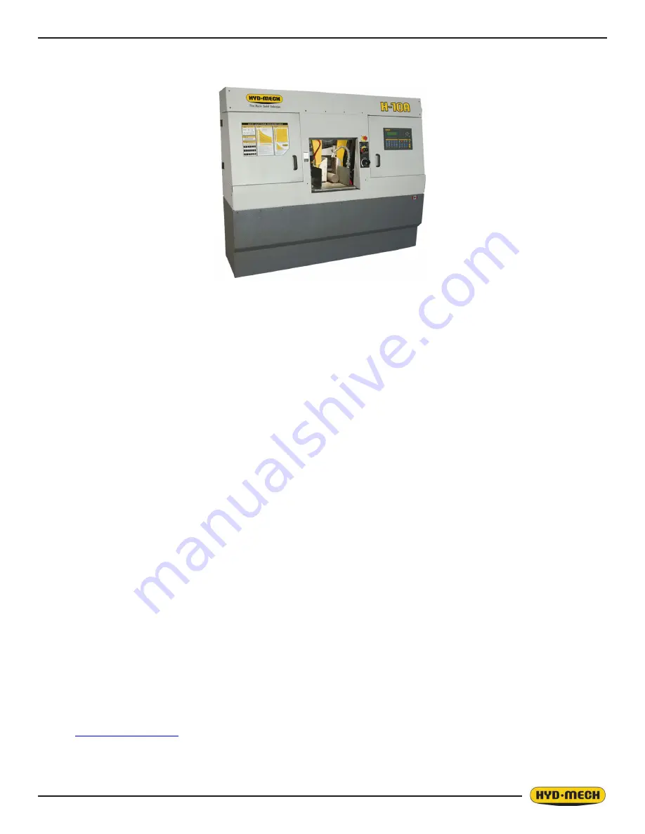
chase a HYD·MECH bandsaw.

Your new machine is now ready to play a key role in increasing the efficiency of your operation, helping you to reduce cost 

while boosting quality and productivity.

To ensure you are maximizing the power and versatility of your new HYD·MECH bandsaw, please take the time to famil-

iarize yourself and your employees with the correct operation and maintenance procedures as outlined in this manual.

We sincerely appreciate the confidence you have demonstrated in purchasing our product and look forward to building a 

long and mutually beneficial relationship.

Thank you

Hyd·Mech Group Limited

P.O. Box 030, 079 Parkinson Road

Woodstock, Ontario, N4S 8A4

Phone : (59) 539-634

Service : -877-237-094

Sales : -877-276-SAWS (7297)

Fax : (59) 539-526
e-mail : 

[email protected]

H10A

393311

REV A

Summary of Contents for H10A

Page 1: ...satility of your new HYD MECH bandsaw please take the time to famil iarize yourself and your employees with the correct operation and maintenance procedures as outlined in this manual We sincerely appreciate the confidence you have demonstrated in purchasing our product and look forward to building a long and mutually beneficial relationship Thank you Hyd Mech Group Limited P O Box 1030 1079 Parki...

Page 2: ......

Page 3: ...ONS 1 3 EARTH GROUNDING PROCEDURE 1 4 HYDRAULIC OIL AND CUTTING FLUID 1 4 SECTION 2 OPERATING INSTRUCTIONS PLC 100 CONTROL SYSTEM 2 1 MANUAL MODE ONLY CONTROLS 2 2 MANUAL AUTO MODE CONTROLS 2 2 MACHINE CYCLE CONTROLS 2 3 PLC CONTROL SYSTEM 2 3 MANUAL MODE 2 4 SINGLE CUT MODE OPERATION 2 4 AUTOMATIC OPERATION 2 5 PROCEDURE FOR EDITING OR STARTING A NEW JOB IN AUTO MODE 2 6 WORKING WITH A QUEUE 2 7 ...

Page 4: ...CAL PROBLEMS 3 9 CUTTING PROBLEMS 3 10 PROGRAMMABLE LOGIC CONTROL 2100 V2 7 SOFTWARE 3 12 PLC PARAMETERS 2100 V2 7 SOFTWARE 3 13 SECTION 4 ELECTRICAL FOR ELECTRICAL SCHEMATICS AND COMPONENTS PARTS LISTS SEE PDF ON ATTACHED CD SECTION 5 HYDRAULIC SYSTEM HYDRAULIC MAINTENANCE REXROTH 5 3 FOR HYDRAULIC SCHEMATICS AND PLUMBING DIAGRAMS SEE PDF ON ATTACHED CD SECTION 6 MECHANICAL ASSEMBLIES FOR MECHANI...

Page 5: ...l materials are within designed specifications and are non hazardous Owner is responsible to keep Manual accessible at the machine ensure only reliable fully trained personnel work with the machine clearly define responsibilities of all personnel working with the machine keep the machine in good working order Operator and Maintenance Personnel are responsible to keep all safety equipment in order ...

Page 6: ...have done over and over Here familiarity boredom or tiredness may lull us into unthinking automatic repetition Be alert for this and when you feel it happening stop and take stock of your situa tion Review the safety hazards associated with what you are doing That should get your brain working again Certainly production is important but if you think you re too busy to put safety first think how mu...

Page 7: ...derstood all parts of Section 0 Safety and Section 2 Operating Instructions Name Date Signature Everyone involved in the installation inspection maintenance and repair of this machine must sign below to confirm that I have read and understood all parts of this Operation and Maintenance Manual Name Date Signature ...

Page 8: ...of Misuse Misuse includes for example Sawing hazardous materials such as magnesium or lead Sawing work pieces which exceed the maximum workload appearing in the Specifications Operating the machine without all original safety equipment and guards Liability The machine may only be operated when it is in good working order and when the operator has read and understood the Safety and Operating Instru...

Page 9: ...nt the foreseeable dangers that may arise during operation of the machine and the safety precautions to be taken In addition the personnel must be instructed to check all safety devices at regular intervals Define responsibilities Clearly define exactly who is responsible for operating setting up servicing and repairing the machine Define the responsibilities of the machine operator and authorize ...

Page 10: ...Safe operation The machine may only be operated when in good working order and when all protective equipment is in place and operational Keep a safe distance from all moving parts especially the blade and vises Stock should not be loaded onto the saw if the blade is running Long and heavy stock should always be properly supported in front of and behind the saw Faults The machine must be switched o...

Page 11: ...ds upon the national regulations in the country in which the machine is being used The actual level of noise emission by band sawing machines depends upon work piece size shape and material blade type blade speed and feed rate The only practical course of action is to measure the actual noise emission levels for the type of work that is typically done With reference to national standards decide up...

Page 12: ...ment establish and post lock out pro cedures Know and use the lock out procedures of your company or organization Residual Risks The machine is still not completely de energized if an electrical cabinet door type switch is locked out The line side of the disconnect switch itself remains energized Variable speed blade drives store dangerous voltage in their capacitors and this requires time to diss...

Page 13: ...ce with your company s lock out procedures before any such maintenance The Stop or Emergency Stop push button does not disconnect the machine s power supply Hazardous voltage is still present in the machines electrical circuits The machine s Electrical Disconnect Switch does disconnect voltage from the machine s circuits however hazardous voltage is still present inside the main electrical cabinet...

Page 14: ...he opening motion of a vise may create potential pinch points MOVING PARTS CAN CRUSH AND CUT Keep hands clear of chip auger Lock out power in accordance with your company s lock out procedures before attempting to clear a jam in the chip auger Be aware that the chip auger may start unexpectedly either because the machine is operating automatically or because another person initiates the motion If ...

Page 15: ...0 11 Danger Moving parts can cut and crush Item No 391335 Danger Hazardous voltage inside Item No 391938 ...

Page 16: ......

Page 17: ...ing shipping contact your carrier to file for a damage claim LIFTING MACHINE This machine is to be lifted in one fully assembled piece In order to lift the machine it needs to be in the following condition Saw head in the down position Shuttle vise fully forward Coolant tank emptied The H10A may be lifted from the FRONT with a forklift which has a minimum capacity of 4500 lbs 2040 kg and a fork le...

Page 18: ...two inside the power pack enclosure and two along the idler side of the machine as shown below Steel plates are provided also shipped in the coolant tank to be placed under each screw to prevent their sinking into the concrete floor In cases when the machine is to be anchored permanently anchoring holes are provided They are located next to the leveling screw holes NOTE In some cases leveling the ...

Page 19: ...e supply voltage to 240V Power connection to the machine is made in the electrical control panel located at the rear of the machine The power ca ble can be routed through the supplied hole at the rear of the machine and connections made to L1 L2 L3 and ground terminals Proper strain relief should be used on the incoming power cable During the initial hook up it is very important to check that the ...

Page 20: ...uctors should originate and connect to DIN terminal strip control transformer and the lid of control enclosure Also PLC and Interface units should have their own ground conduc tors connected to one of the main ground terminals 6 Properly functioning ground system will Provide safety for personnel Ensure correct operation of electrical electronic devices Prevent damage to electrical electronic appa...

Page 21: ...anel to full ON and the display back light will come ON Once the control panel has power the MACHINE START key must be pressed to activate the interface which will also start the hydraulic system Now all of the control keys have been activated and each key has an LED to indicate which functions are active In MANUAL MODE the operator has the ability to execute a single cut utilizing a pre programme...

Page 22: ... will move FAST Pressing the key will switch this function back to SLOW MANUAL AUTO MODE CONTROLS BLADE CONTROLS BLADE START Pressing this key will start the blade The blade will not start if the head is fully down BLADE STOP Pressing this key will stop the blade BLADE SPEED Pressing this key will cause the blade speed to increase until the key is released or the speed is at the maximum 350 SFM Th...

Page 23: ...SYSTEM The PLC operator interface occupies the upper left corner of the console and is used in all four operating modes 1 Manual Mode permits the operator to control all machine functions using the pushbuttons as well as the opera tor interface function keys 2 Single Cut Mode permits the operator to enter part length and then advance and cut a single part automatically 3 Automatic Job Mode is used...

Page 24: ... the blade is above the material 4 ENTER LENGTH will be flashing Key in the desired length up to 214 5436 mm using the numeric keypad and press enter 5 Cycle start will be flashing in the display window 6 Press the cycle start pushbutton The pushbutton lights and the Material Height Prompt Screen appears MANUAL MODE BLADE SPEED 0 SFM FEED RATE 0 M LENGTH 0 SHUTTLE OVERTRAVELLED DISPLAY NOT REFEREN...

Page 25: ...ements will immediately cease except blade will continue to run To continue the cycle press CYCLE START 2 To cut multiple pieces switch to AUTO MODE and follow the automatic procedures 3 Whenever a new job or new material is being loaded for production the head up limit switch should be properly set to clear the material positioned for a trim cut and the front vise should be closed in MANUAL MODE ...

Page 26: ...in memory with the new values The job is now ready to start to run or other jobs can be programmed at this time To run a certain job press the QUEUE key and then CLEAR to clear the QUEUE Move the cursor to the 1st job and key in the desired JOB 2 After the values are entered press the CYCLE START button The pushbutton lights and the Material Height Prompt Screen appears 3 Set the material height u...

Page 27: ...eds NUMBER OF PIECES AUTO CYCLE will not start WORKING WITH A QUEUE The purpose of a QUEUE is to allow the operator to run several jobs maximum of 5 in series if they are of the same material and shape To run a QUEUE it is necessary to program in all job values as is done with programming a single job After the jobs are programmed in press QUEUE press CLEAR to clear the QUEUE and enter the desired...

Page 28: ...de can also be set to repeat the sequence of jobs up to 99 times To do this the QUEUE parameter in SERVICE mode must be set at REPEAT To run a repeating queue two additional rows are added to the QUEUE display screen after JOB E QUEUE CUT the number of times that the QUEUE has been completed and QUEUE REQUIRED the number of times that the QUEUE is required to be repeated When entering job data for...

Page 29: ... blade encounters little or no resistance as when cutting thin cross sections or falling freely without any work piece The FEED FORCE VALVE FFV sets the degree of slow down as the blade encounters resistance from the work piece 0 results in extreme slowing of feed and 100 results in limited but perceptible slowing of feed as resistance is en countered ...

Page 30: ...f materials is the widest solid part of the material to be in con tact with blade during cutting For simple shapes as illustrated on the chart this can be directly measured For bundles of tubes and structurals measuring the effective width is difficult Effective width is 60 to 75 of the actual material width NOTES 1 Both effective material width and guide arm width are used in setting the saw 2 Gu...

Page 31: ... directly across to the vertical FF Setting line The point that you have ar rived at shows a setting of 40 for a piece 50 of capacity STEP 3 DETERMINE OPTIMUM BLADE PITCH TEETH PER INCH T P I Selecting a blade with proper tooth pitch is important in order to achieve optimal cutting rates and good blade life For cutting narrow or thin wall structural materials a fine blade with many teeth per inch ...

Page 32: ...ection point run horizontally left to the vertical axis optimum blade speed axis and find the point marked 200 For an 8 200mm diameter 1045 Carbon Steel solid bar 200 ft min 60m min is the optimum blade speed NOTE 1 Higher than optimum blade speed will cause rapid blade dulling Lower than optimum blade speeds reduce cutting rates proportionately and do not result in significantly longer blade life...

Page 33: ...quired value If you turn too far the knob should be turned back to 0 and back to the required value To set FEED RATE for particular cutting situations use the graph below which represents the relationship between FEED RATE blade speed and blade pitch For Example 1 it is known from STEP 3 that optimum blade pitch is 2 3 and from STEP 4 that blade speed is 200 ft min 60m min From the graph on the le...

Page 34: ...e g TPI we use the graph for the optimum blade as before and then use a multiplier given by the table below Once the Feed Rate has been set to an optimum value it is a good idea to make a test cut and raise or lower Feed Force setting as needed so that 1 Feed rate in wide sections does not drop too low 1 3 of maximum Feed Rate in wide sections of structurals of maximum Feed Rate in solid rounds Fu...

Page 35: ...Feed Force Limit setting in Step 2 3 Optimum blade pitch TPI TPI 4 Optimum blade speed for 5 effective material width 320 ft min 100m min 5 Feed Rate for TPI blade 4 0 in min or 100mm min OTHER HYDRAULIC CONTROLS OPTIONAL Bundling Clamp Valves The bundling clamps can be used to supplement the front and shuttle vises by clamping down on the work piece from above As the name implies they are particu...

Page 36: ... speed because the auger starts automatically with the head feed MECHANICAL CONTROLS Out of stock Collar The collar is located on the lower guide shaft of the Shuttle Vise and is locked in position by a brass thumbscrew The action of the collar is to trip a limit switch and shut down the saw when the shuttle vise closes without encountering a work piece The Out of stock collar must be reset for ea...

Page 37: ...of cool ant to the blade When cutting wide work pieces the flexible nozzle should be used to direct extra coolant into the saw kerf at about mid span of the cut Mist Coolant Optional the air powered pump delivers a regulated number of pulses of lubricant to a single applicator nozzle The unit has two control screws Pulse Minute adjusts the rate of lubricant use About 8 to 12 pulses per minute is o...

Page 38: ......

Page 39: ...a the following steps shall be taken 1 Operator shuts down the machine The head must be lowered fully or onto suitable supports before any hydraulic service is performed to prevent the head from moving unexpectedly 2 The supervisor in charge of the machine must be informed of the intention to lock out the machine 3 The main power disconnect switch must be turned off and locked in the off position ...

Page 40: ...op of the head the blade runs in a protective channel Grip the blade at each end of this channel and twist the blade teeth down to the opening in the channel and slide the top of the blade forward Let this portion of the blade rest on the outfeed table then slide the rest of the blade down and out of the blade guide blocks The new blade will be supplied in a coil While wearing gloves hold the blad...

Page 41: ...nspect the blade wheels for wear or damage and repair as required Blade tracking adjustment should always begin at the wheel where the tracking is farthest out of specification Using the instructions below adjust the worst wheel jog the blade and then check both wheels Repeat this process until both wheels are within specification 200 220 5mm to 5 6mm of tooth overhang from the front of the wheel ...

Page 42: ...semblies consisting of carbide pads that are integral to the correct guidance of the saw blade These guide assemblies will require an adjustment periodically refer to Troubleshooting in this section for indications that adjustment is needed To adjust the pads properly follow this simple procedure With the lever in the locked position loosen the small set screw A in the edge of the lever Turn the a...

Page 43: ...y against the blade There is also an adjusting socket set screw with a hex nut on it Loosen the hex nut with a 9 16 wrench and turn the set screw counter clockwise with a 3 16 allen key This will move the brush closer to the blade Adjust the set screw so that the brush cleans to the bottom of the blade gullets and tighten the hex nut If the brush gets worn to approximately 70 of its original 3 dia...

Page 44: ...3 6 Shuttle Linear Bearings x4 Movable Guide Arm Linear Bearings x2 ...

Page 45: ... 6 month intervals with lithium based grease To re lubricate the ball screw grease fitting 1 As with linear bearings grease should be pumped slowly until fresh grease exits from the unit 2 Run the shuttle fully back and then forward to the home position at least twice in SLOW mode before resuming normal use ...

Page 46: ...so have the necessary EP and anti foaming additives TROUBLE SHOOTING GUIDE Most problems that occur have one of the relatively simple solutions that appear in this section If the solution is not found here contact the HYD MECH distributor from whom you purchased your bandsaw They have trained field service personnel who will be able to rectify the problem NOTES 1 IF THE BLADE IS RUNNING CLOCKWISE ...

Page 47: ...lic pump motor starts but a hydraulic function does not respond to selector switch Pressure on gauge 3 1 If LED on cord connector at valve solenoid lights but no function Solenoid failure or valve stuck 3 1 Interchange coils with other valve If fault follows coil replace coil If fault stays with valve replace valve 3 2 If LED on cord connector does not light but corresponding LED at PLC output lig...

Page 48: ...elow 0 20 in min 6 5 Stock misalignment 6 5 Check that stock rests evenly on conveyor rollers 6 5 Worn blade guide rollers 6 5 Replace guide assemblies with interchange assembly kits 7 Saw is cutting out of square horizontally 7 1 Stock misalignment 7 1 Check for bowed stock Re arrange stock 7 2 Worn blade guide rollers 7 2 Replace guide assemblies with interchange assembly kits 8 Blade comes off ...

Page 49: ...rong blade for workpiece material 13 3 Seek advice ofblade supplier or Hyd Mech dealer 13 4 Ineffective cutting fluid 13 4 Check fluid cleanliness and concentration Seek advice of fluid supplier or Hyd Mech dealer 14 No or low cutting fluid flow 14 1 Fluid level in tank is too low 14 1 Add cutting fluid 14 2 Fluid line s blocked 14 2 Clear line s with compressed air Wear suiutable eye protection 1...

Page 50: ...uttle Servo Motor Encoder Shuttle Home and Shuttle Overtravel Limit Switches Out of stock Limit Switch Blade Speed Proximity Switch Blade Door and Shuttle Guard Interlock Switches PLC Parameters are a table of normally fixed values what can be modified to adjust the way in which the machine oper ates To gain access to the Parameters either to observe the current settings or to make changes In Manu...

Page 51: ...le Vise Opening motion CLOSE TIME 1 0s Delay from start of Shuttle Vise Closing to start of Shuttle Forward motion ACTUAL POSITION DISPLAY NO YES NO If YES selected the length display will show actual position of the shuttle BLADE TENSION SENSOR BYPASS NO YES NO NO machine will not run with a damaged Blade Tension sensor YES enables machine to run with damaged Blade Tension sensor but no blade ten...

Page 52: ...p the shuttle will retract the material away from the blade by 1 8 before the head will move up When the head gets to the up position the next length will be shuttled into position COOLANT BLD BLD BLD DWN Auto Coolant Mode requires Coolant Switch to be in Auto position BLD Coolant flows when blade is running BLD DWN Coolant flows when blade is running and head is descending QUEUE SINGLE The QUEUE ...

Page 53: ...4 1 FOR ELECTRICAL SCHEMATICS AND COMPONENTS PARTS LISTS SEE PDF ON ATTACHED CD SECTION 4 ELECTRICAL ...

Page 54: ......

Page 55: ... C21 00 VISE CYLINDER 3 0 2 H10 C23 00B BUNDLING CYLINDER option 4 1 DDF1 0 00A DDF VALVE 5 8 1 362748 DCV3P AB T HEAD CONTROL VALVE 6 9a 9b 2 362749 DCV3P AB C VISE VALVE 7 7 1 362747 DPCH 1 DOUBLE PILOT CHECK VALVE 8 2 1 362752 PUMP 9 3 1 362753 MOTOR 240 VAC 1Hp Three phase 10 1 362756 FILTER ELEMENT 11 0 1 362758 VARIABLE VISE PRESSURE BLOCK VVP option 12 0 1 363145 PRESSURE REDUCING VALVE VVP...

Page 56: ...iller Breather Cleanout Cover System Pressure Gauge Drain Plug Pump Pressure Adjustment Oil level should be maintained at the top portion of the level gauge glass window Filler cap and filter element location Oil level gauge and drain plug ...

Page 57: ... will be very low and it should be unnecessary to add oil more often than at filter changes if at all The usable volume of oil reservoir is 4 US Gallons 4 HYDAULIC OIL CHANGE Oil visual inspection should be conducted with every filter change for following signs of degradation Milky or hazy oil color Burnt smell Varnish or sludge formation Increased viscosity If one of the above is observed then oi...

Page 58: ......

Page 59: ...6 1 FOR MECHANICAL ASSEMBLY DRAWINGS SEE PDF ON ATTACHED CD SECTION 6 MECHANICAL ASSEMBLIES ...

Page 60: ......

Page 61: ...7 1 FOR OPTIONAL ASSEMBLIES SEE PDF ON ATTACHED CD SECTION 7 OPTIONS ...

Page 62: ......

Page 63: ...n linear bearings Motors blade drive 5 HP 3 7 kW hydraulic pump drive 1 HP 75 kW Hydraulic Tank 4 U S Gallons 15 Liters Coolant Tank 6 6 U S Gallons 25 Liters System Pressure 600 PSI 4137 kPa Vise Control Hydraulic Full Stroke Shuttle Stroke 0 24 0 610mm single stroke multi index capability Discharge Table 10 254mm Table Height 31 787mm Machine Weight 2500 lbs 1134 Kg Overall Dimensions 83 2111mm ...

Page 64: ...8 2 H10A LAYOUT ...

Page 65: ...ufacture of the H10A but not originally manufactured by Hyd Mech are subject to the original manufacturer s warranty Hyd Mech will provide such assistance and information as is necessary and available to facilitate the user s claim to such other manufacturer Liability or obligation on the part of Hyd Mech for damages whether general special or for negligence and expressly including any incidental ...

Page 66: ...T HGT CONSTANT SHUTTLE FULL STROKE LGT CONSTANT ACCEL DECEL MAX SHUTTLE SPEED FVO DWELL SVO DWELL CLS TIME ACTUAL POS DISPLAY BLADE TENS SENS BYPASS BROKEN PROXY MIN BLADE SPEED SPD PROXY DELAY POWER DWN TIMER TRIM CUT BLADE CLEAR COOLANT QUEUE ...

Reviews: