HYBREX GDS-600, Installation Manual
The HYBREX GDS-600 is a versatile communication system designed for businesses. Ensure smooth installation with our comprehensive Installation Manual available for free download from manualshive.com. This manual provides step-by-step instructions and essential details to set up your GDS-600, ensuring seamless communication within your organization.
Share
Download


Reviews:
No comments
Related manuals for GDS-600

UX5000
Brand: NEC Pages: 334

AccuSync 120
Brand: NEC Pages: 12

KX-TA1232
Brand: Panasonic Pages: 92

KX-TA1232
Brand: Panasonic Pages: 16

MDV-8
Brand: LENCO Pages: 27

DXAI5688-2 - DXAI Cordless Phone
Brand: Uniden Pages: 68

DXAI4288-2
Brand: Uniden Pages: 72

onetouch 4022S
Brand: TCL Pages: 21

JHS-207
Brand: JRC Pages: 110

DE151
Brand: switel Pages: 88

CD6229i
Brand: Audiovox Pages: 15

Payphone Contour 400
Brand: BT Pages: 36

SX-06L
Brand: QBest Pages: 17

MXA70
Brand: McIntosh Pages: 32

DHT 700
Brand: AKG Pages: 29
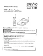
CAS-A900
Brand: Sanyo Pages: 38

C-616DV
Brand: Kenwood Pages: 17

AVS-1003B
Brand: Kenwood Pages: 2


