background image


HX-200/Linear Installation Procedure 

Revision A.04 


When installing a Pre-Commissioned HX 200 follow the procedure in Appendix C 

1.


Assemble and install the antenna mount as per instructions included with unit. 

2.


Assemble the antenna and install on the mount as per instructions included with unit 

3.


Pull and terminate 2 IFL cables from the antenna location to the HX-200 IDU location 

4.


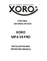
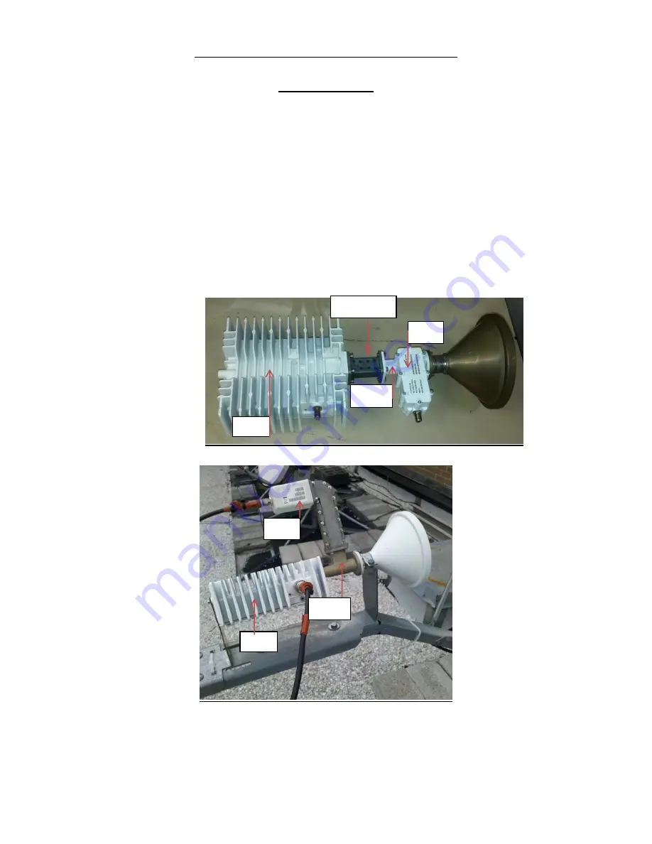
Assemble the Linear Radio (BUC, LNB, OMT, Transition, and Feed horn.  Attach the assembly to 

the antenna.  Reference Appendix A (this instruction also included with the unit) 


5.


Connect the IFL cables to RFU and HX200


BUC 

LNB 

OMT 

OMT 

LNB 

Transition 

BUC 

Summary of Contents for HX200

Page 1: ...Assemble the antenna and install on the mount as per instructions included with unit 3 Pull and terminate 2 IFL cables from the antenna location to the HX 200 IDU location 4 Assemble the Linear Radio BUC LNB OMT Transition and Feed horn Attach the assembly to the antenna Reference Appendix A this instruction also included with the unit 5 Connect the IFL cables to RFU and HX200 BUC LNB OMT OMT LNB ...

Page 2: ...back bin version on the upper left corner on the advanced page on the HX200 Update the HX200 with the Fallback updater ONLY if the version is not equal or greater than the version from the install portal See Appendix B for detailed procedure 10 Upload the SBC cfg file latest version on the portal select Config File Upload Green arrow and browse to the folder on the laptop which contains the sbc fi...

Page 3: ...Satellite Parameters page Make note of the Receive Polarization This will be needed to calculate the course polarization in a following step Select Next 15 Select the appropriate LNB type from the pull down menu then select Next This will bring up the verification page Select Next to move on to TX Radio Parameters ...

Page 4: ...m Attenuation The Ranging Initial Attenuation is the Minimum Attenuation plus six 6 Example Radio Gain 63 db Radio Max Power 38 dbm IFL loss 10 db 63 38 25 25 10 15 Minimum Attenuation 15 6 21 Ranging Initial Attenuation 18 Enter these values and Select Next 19 The Tx Verification page will be displayed Once the values are verified select Next The Rx Antenna Pointing page is displayed 20 This page...

Page 5: ...the RFU Note that the RFU pictured below is currently set to Zero 0 23 Once the coarse antenna pointing values shown above have been obtained and the DAPT is inline on the Rx IFL cable at the RFU select Display Signal Strength and begin the antenna pointing process as seen at the DAPT 24 Peak the antenna for the best obtainable SQF by adjusting the Azimuth and Elevation of the Antenna Once complet...

Page 6: ...ardware and close the window that displayed the test results 27 Select Automatic for one final check 28 Once complete close the window that displayed the test results and select Next 29 The server is displayed in the pull down box Select Next 30 The following status page is displayed Once the Click Next to continue message is displayed Select Next ...

Page 7: ...that of the unit you will be attempting to register 32 Once the serial number has been verified and the Site ID correctly entered select Continue You will be Prompted to Please Wait while unit is registering with the Network 33 The following will be displayed once complete Select Continue ...

Page 8: ...of configuration data 34 When the Terminal Reset screen is displayed Select Close The unit will reset 35 Once the unit has completed the reset log back into the System Control Center using your laptop Web browser Your laptop IP Address may need to be configured at this time if the HX 200 LAN configuration does not have DHCP enabled You may also need to enter the LAN 1 IP Address of the HX200 in th...

Page 9: ...re Download Status is indicating All files are up to date It may take a minute or so for this status to update In order to check ranging rates Select the Icon on the SCC to gain access to the Advanced page From the left hand menu select Installation then Ranging Stats The Successful Rates should include the rate expected for this site 39 The HX 200 Installation is now complete ...

Page 10: ...10 Appendix A RFU Antenna Assembly ...

Page 11: ...ate to the default directory where the files were unzipped The latest version is found on Portal and loaded to the installers PC Double click on HUGHES_Updater Results The following messages will be generated if the fallback update operation is successful STEP 1 Click on the Accept button to acknowledge the restricted use condition STEP 2 Click on the OK button to begin the update process ...

Page 12: ...12 STEP 3 STEP 4 ...

Page 13: ...13 ...

Page 14: ...14 After the above operation is completed the user interface automatically exits After the unit boots up verify on the Advanced page that the banner date of the software is correct ...

Page 15: ...row 2 Select the Installation tab Blue Arrow in the left hand column Select Setup and once the page comes up select VSAT Manual Commissioning Green Arrow Arrow 3 Select VSAT Parameters 4 Enter your Latitude and Longitude taken by your GPS at the antenna location 5 Select Transmit Parameters ...

Page 16: ...o Max Power IFL loss Subtract the Radio Max power from the Radio Gain Subtract the IFL loss from the value calculated in the previous step This value will be the Minimum Attenuation The Ranging Initial Attenuation is the Minimum Attenuation plus six 6 Example Radio Gain 63 db Radio Max Power 38 dbm IFL loss 10 db 63 38 25 25 10 15 Minimum Attenuation 15 6 21 Ranging Initial Attenuation 7 Select Li...

Page 17: ...ice select Enable OPI before clicking Next 12 Select Display Signal Strength Point and Peak the Antenna for best SQF value 13 Close Signal Strength Test and check Perform ACP Select Next 14 Run ACP and set the polarization and peak for the best Isolation ...

Page 18: ...18 15 Exit Antenna Pointing 16 Select Force Range Start Ranging 17 Once ranging is complete the HX 200 should now be ready for use ...

Reviews: