


1
Safety Information
OceanStor CloudStor CSE V100R001C01
Quick Installation Guide
Issue:
03
Date:
2012-10-17
Do not operate devices or handle cables on a stormy day.
To avoid personal injuries, take off your electrostatic discharge (ESD) wrist strap before inserting a power cable.
To avoid personal injuries, arrange enough persons to carry the devices according to the suggestion on the package.
Before handling devices, wear an ESD suite, ESD gloves, or an ESD wrist strap and take off conductive objects such
as ornaments and watches.
To avoid device damage, ensure that the devices are grounded before powering them on.
Do not insert or remove disks or cables during power-on of the CSE. When data is being read or written on hard
disks, do not power off the device by cutting off power or holding down the power button for seconds. Otherwise, the
hard disks may have bad tracks and data may be damaged. To power off the device, stop reading and writing data on
the hard disks first and then send a shutdown command through the operating system (OS).
Copyright © Huawei Technologies Co., Ltd. 2012. All rights reserved.
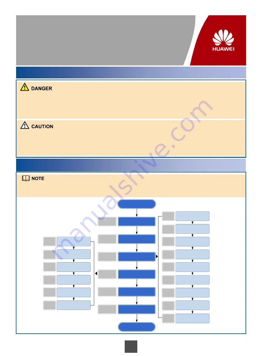
Installation Process
The power distribution system (DC or AC power distribution box), auxiliary tools (guide rails and floating nuts) are
pre-installed and cables (including power cables and network cables) are laid out in the system cabinet of the CSE
before delivery.
确定
T3200 G3
在机柜中的位置
Prepare the materials and
installation tools.
Take antistatic measures.
Install hardware devices of
the CSE.
Connect cables.
Power on the devices and
check indicator status.
Install software.
Start
End
Page 2
Page 14
Page 12 to 13
Page 7 to 11
Page 4 to 7
Page 3
Determine positions of
devices in the cabinet.
Remove filler panels.
Install back-end storage
devices.
Install a KVM.
Install a switch.
Install a SD-Node.
Page 4
Page 5
Page 5
Page 5
Page 5
Page 6
Install a C-Node.
Install a SMS modem.
Page 6
Page 6
Connect the SD-Node.
Connect the C-Node.
Connect the switch.
Connect the KVM.
Connect the SMS modem.
Connect the remote modem.
Page 10
Page 10
Page 11
Page 11
Page 11
Page 11
Install a Remote modem.
Page 7


