background image

120 Braley Rd. P.O. Box 429 

                         East Freetown, MA 02717-0429                                    www.htproducts.com


LP- 293 REV. 3.29.12
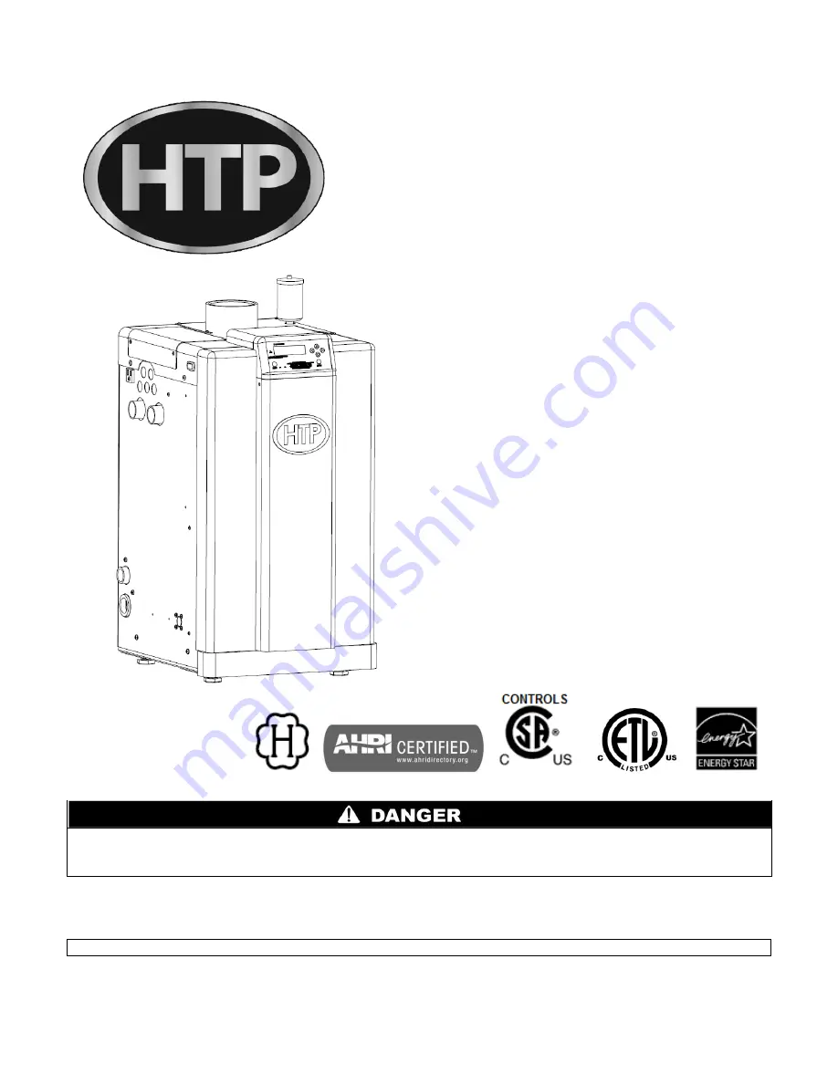
 

Elite 


INSTALLATION 


START-UP 


MAINTENANCE 


PARTS 


Elite Models* 

EL-80 / 110 / 150 / 220 / 299 / 399 


*A suffix of “LP” denotes propane gas 

*A suffix of “N” denotes natural gas 


NOTICE:

 HTP reserves the right to make product changes or updates without notice and will not be held liable for 

typographical errors in literature. 
 

NOTE TO CONSUMER: PLEASE KEEP ALL INSTRUCTIONS FOR FUTURE REFERENCE. 


This manual must only be used by a qualified heating installer/service technician. Read all instructions in this 
manual before installing. Perform steps in the order given. Failure to comply could result in substantial property 
damage, severe personal injury, or death. 

Summary of Contents for EL-110

Page 1: ...rves the right to make product changes or updates without notice and will not be held liable for typographical errors in literature NOTE TO CONSUMER PLEASE KEEP ALL INSTRUCTIONS FOR FUTURE REFERENCE This manual must only be used by a qualified heating installer service technician Read all instructions in this manual before installing Perform steps in the order given Failure to comply could result ...

Page 2: ... THIS OR ANY OTHER APPLIANCE WHAT TO DO IF YOU SMELL GAS Do not try to light any appliance Do not touch any electrical switch Do not use any phone in your building Immediately call your gas supplier from a neighbor s phone Follow the gas supplier s instructions If you cannot reach your gas supplier call the fire department Installation and service must be provided by a qualified installer service ...

Page 3: ... Having Jurisdiction local code authorities and utility companies which pertain to this type of water heating equipment Authority Having Jurisdiction AHJ The Authority Having Jurisdiction may be a federal state local government or individual such as a fire chief fire marshal chief of a fire prevention bureau labor department or health department building official or electrical inspector or others ...

Page 4: ...rmance criteria when the boiler underwent tests specified in ANSI Z21 13 latest edition The hydronic supply and return connections of these products are for installation in closed loop systems ONLY Use of this product in any manner other than described in this manual may result in premature product failure substantial property damage severe personal injury or death Damage or failure of this produc...

Page 5: ... N ZONING WITH CIRCULATORS 32 O MULTIPLE BOILERS 32 PART 5 VENTING COMBUSTION AIR AND CONDENSATE REMOVAL 33 A GENERAL 33 B APPROVED MATERIALS FOR EXHAUST AND INTAKE AIR VENTS 34 C REQUIREMENTS FOR INSTALLATION IN CANADA 35 D EXHAUST VENT AND INTAKE AIR VENT PIPE LOCATION 36 E EXHAUST VENT AND INTAKE AIR VENT SIZING 39 F LONGER VENT RUNS 40 G EXHAUST VENT AND INTAKE AIR PIPE INSTALLATION 40 H SIDEW...

Page 6: ...RING 59 N CASCADE FOLLOWER PUMP AND SENSOR WIRING 59 PART 8 START UP PREPARATION 63 A CHECK CONTROL WATER CHEMISTRY 63 B CHECK FOR GAS LEAKS 64 C FREEZE PROTECTION WHEN USED 64 D FILL AND TEST WATER SYSTEM 64 E PURGE AIR FROM WATER SYSTEM 65 F CHECK THERMOSTAT CIRCUIT S 66 G CONDENSATE REMOVAL 66 H FINAL CHECKS BEFORE STARTING BOILER 67 I CASCADE SYSTEM 67 J LOCKOUT CONDITION 68 PART 9 START UP PR...

Page 7: ... Front must have room for service 24 recommended A combustible door or removable panel is acceptable front clearance This appliance has been approved for closet installation Do not install this appliance directly on carpeting For installation on combustible flooring Category IV vent systems only INSTALLER Read all instructions in this manual before installing Perform steps in the order given USER ...

Page 8: ...he boiler with regard to heating system load will result in excessive cycling and accelerated component failure HTP DOES NOT warrant failures caused by improperly sized boiler applications DO NOT oversize the boiler to the system Modular boiler installations greatly reduce the likelihood of boiler oversizing B IMPROPER COMBUSTION C GAS Should overheating or gas supply fail to shut off do not turn ...

Page 9: ...ove 7 grains hardness Chlorine concentration less than 100 ppm o Using chlorinated fresh water should be acceptable as levels are typically less than 5 ppm o Do not connect the boiler to directly heat swimming pool or spa water o Do not fill boiler or operate with water containing chlorine in excess of 100 ppm NOTE It is recommended to clean heat exchanger at least once a year to prevent lime scal...

Page 10: ... to monitor outdoor temperature through an outdoor sensor to regulate boiler set point The system can be further enhanced by installing an indirect water heater to provide domestic hot water The control can regulate the output of multiple boilers through its cascade system function The cascade system is capable of connecting up to eight boilers together in such a way that they function as one boil...

Page 11: ...ler Condensate Flue Check System The check system prevents exhaust from the heat exchanger from backing up into cabinet Pump Service Mode Allows manual operation of pumps to commission system and check pump operation The Vision II System Optional Allows the user to supply mixed temperatures in up to eight zones The Vision II system controls the temperature to each zone by employing three way mixin...

Page 12: ...Never close existing ventilation openings The service life of the boiler s exposed metallic surfaces such as the casing as well as internal surfaces such as the heat exchanger are directly influenced by proximity to damp and salty marine environments In such areas higher concentration levels of chlorides from sea spray coupled with relative humidity can lead to degradation of the heat exchanger an...

Page 13: ... substantial property damage and could result in severe personal injury or death Use extreme care not to drop the boiler or cause bodily injury while lifting or mounting the boiler onto the optional wall mount bracket Failure to do so will result in property damage and could result in severe personal injury or death Gas conversion should be performed BEFORE the boiler is installed Carefully follow...

Page 14: ...cated in the same space as the boiler The boiler cover must be securely fastened to prevent it from drawing air from the boiler room This is particularly important if the boiler is in a room with other appliances Failure to comply with the above could result in substantial property damage severe personal injury or death MINIMUM CLEARANCES FROM COMBUSTIBLE MATERIALS Hot water pipes at least 1 from ...

Page 15: ...15 Figure 3 ...

Page 16: ...ler is located in a residential garage per ANSI Z223 1 Mount the bottom of the boiler a minimum of 18 above the floor of the garage to ensure the burner and ignition devices are well off the floor Locate or protect the boiler so it cannot be damaged by a moving vehicle ...

Page 17: ...BUSTION AIR CONTAMINATION Install intake piping for the boiler as described in the Venting section Do not terminate exhaust in locations that can allow contamination of intake air Ensure that the intake air will not contain any of the contaminants below For example do not pipe intake vent near a swimming pool Avoid areas subject to exhaust fumes from laundry facilities These areas always contain c...

Page 18: ...eration the appliance being inspected Follow the lighting instructions Adjust the thermostat so the appliance will operate continuously 5 Test for spillage at the draft hood relief opening after 5 minutes of main burner operation Use the flame of a match or candle or smoke from a cigarette 6 After it has been determined that each appliance remaining connected to common venting system properly vent...

Page 19: ...e connected to an indirect water heater to supply domestic hot water HTP offers indirect water heaters in a wide range of gallon sizes in either stainless steel or glass lined construction A GENERAL PIPING INFORMATION The building piping system must meet or exceed the piping requirements in this manual Use two wrenches when tightening water piping at the boiler Use one wrench to prevent the boiler...

Page 20: ...valve does not operate turn the boiler off and call a plumber immediately Take care whenever operating relief valve to avoid scalding injury or property damage For boilers installed with only a pressure relief valve the separate storage vessel must have a temperature and pressure relief valve installed This relief valve shall comply with Relief Valves for Hot Water Supply Systems ANSI Z21 22 CSA4 ...

Page 21: ...turn to the tank to provide an air cushion An automatic air vent would cause air to leave the system resulting in improper operation of the expansion tank DIAPHRAGM OR BLADDER EXPANSION TANK Always install an automatic air vent on top of the air separator to remove residual air from the system E CIRCULATORS DO NOT install automatic air vents on closed type expansion tank systems Air must remain in...

Page 22: ...circulation of boiler water in the coils during the cooling cycle Chilled water medium must be piped in parallel with the boiler Freeze protection for new or existing systems must use glycol that is specifically formulated for this purpose Antifreeze must include inhibitors that will prevent the glycol from attacking the metallic system components Make certain that the system fluid is checked for ...

Page 23: ...e upstream of all circulators 4 Piping shown is Primary Secondary 5 System flow secondary loop should be greater than the boiler primary loop flow In all cases the boiler primary loop flow rate must be maintained above the minimum flow rates published on p 28 this manual 6 Installations must comply with all local codes 7 In Massachusetts a vacuum relief valve must be installed in the cold water li...

Page 24: ...s 4 Piping shown is Primary Secondary 5 System flow secondary loop should be greater than the boiler primary loop flow In all cases the boiler primary loop flow rate must be maintained above the minimum flow rates published on p 28 this manual 6 Installations must comply with all local codes 7 In Massachusetts a vacuum relief valve must be installed in the cold water line per 248 CMR 8 Reference F...

Page 25: ...aight pipe upstream of all circulators 3 Piping shown is Primary Secondary 4 System flow secondary loop should be greater than the boiler primary loop flow In all cases the boiler primary loop flow rate must be maintained above the minimum flow rates published on p 28 this manual 5 Installations must comply with all local codes ...

Page 26: ...aight pipe upstream of all circulators 3 Piping shown is Primary Secondary 4 System flow secondary loop should be greater than the boiler primary loop flow In all cases the boiler primary loop flow rate must be maintained above the minimum flow rates published on p 28 this manual 5 Installations must comply with all local codes ...

Page 27: ...erating It should read a minimum pressure of 12 psi 6 Install a circulator as shown in piping details this section Make sure the circulator is properly sized for the system and friction loss 7 Install an expansion tank on the system supply see Part 4 Section D for water volume Consult the expansion tank manufacturer s instructions for specific information relating to expansion tank installation Si...

Page 28: ... 19 GPM 20 GPM EL 80 2 5 3 4 7 10 14 17 21 26 EL 110 3 4 7 9 12 15 17 22 25 33 EL 150 3 4 5 6 9 10 12 15 17 19 22 27 EL 220 2 2 3 4 5 5 5 6 12 8 10 11 5 13 15 16 5 EL 299 3 3 5 4 4 5 5 6 7 8 8 75 9 25 10 25 11 13 EL 399 3 8 4 5 6 6 6 7 7 8 8 3 Flow Rate 21 GPM 22 GPM 23 GPM 24 GPM 25 GPM 26 GPM 27 GPM 28 GPM 29 GPM 30 GPM 31 GPM 32 GPM 33 GPM 34 GPM 35 GPM 36 GPM 37 GPM 38 GPM 39 GPM EL 80 EL 110 ...

Page 29: ...ANTY Sodium less than 20 mGL Water pH between 6 0 and 8 0 1 Maintain boiler water pH between 6 0 and 8 0 Check with litmus paper or have chemically analyzed by water treatment company 2 If pH differs from above consult local water treatment company for treatment needed Hardness less than 7 grains Consult local water treatment companies for unusually hard water areas above 7 grains hardness Chlorin...

Page 30: ...ufacturer s instructions to verify inhibitor level and that other fluid characteristics are satisfactory 2 Freeze protection fluid must be replaced periodically due to degradation of inhibitors over time Follow all fluid manufacturer instructions Piping components Heating system piping Water boiler system piping MUST be sized per technical pipe requirements listed in Table 5 and Table 6 Reducing p...

Page 31: ...urthest air vent It may be necessary to install a basket strainer in an older system where larger amounts of sediment may be present Annual cleaning of the strainer may be necessary Upon completion make sure that the fill valve and zone valves are in automatic positions You must also assure the purge and shut off valves are in open positions L GLYCOL ANTIFREEZE SOLUTIONS Use only inhibited propyle...

Page 32: ...o indirect storage water heater as shown in Piping Details N ZONING WITH CIRCULATORS 1 When using circulator zoning connect the boiler to the system as shown in Piping Details Part 4 Section G NOTE The boiler circulator cannot be used for a zone It must only supply the boiler loop 2 Install a separate circulator for each zone 3 Connect DHW domestic hot water piping to indirect storage water heater...

Page 33: ...th these instructions and with the National Fuel Gas Code ANSI Z223 1 NFPA 54 CAN CGA B149 and or applicable provisions of local building codes 3 This boiler must be vented with materials components and systems listed and approved for Category IV boilers Exhaust and intake air pipes are to be piped separately This boiler cannot share a common exhaust or intake with multiple appliances Failure to f...

Page 34: ...en using an HTP PVC termination kit DO NOT mix AL 29 4C piping from different manufacturers unless using adapters specifically designed for the purpose by the manufacturer Failure to follow these directions will result in substantial property damage severe personal injury or death Table 8 NOTES 1 Air inlet piping does not require high temperature pipe material Check applicable local codes for acce...

Page 35: ...inspection 3 The components of the certified vent system must not be interchanged with other vent systems or unlisted pipe fittings Cellular foam core piping may be used on air inlet piping only NOTE The use of double wall vent or insulated material for the air inlet is recommended in cold climates to prevent the condensation of airborne moisture in the incoming combustion air You must not use B v...

Page 36: ...r below the aforementioned equipment unless the 4 foot horizontal distance is maintained Do not locate the boiler exhaust over public walkways where condensate could drip and or freeze and create a nuisance or hazard When adjacent to a public walkway locate exit terminals at least 7 feet above grade To prevent icicles from forming do not locate the exhaust directly under roof overhangs Provide 6 f...

Page 37: ...iler is slightly acidic with a pH of 3 2 4 5 To avoid long term damage to the drainage system and to meet local code requirements HTP recommends neutralizing the condensate with a Condensate Neutralizer Kit Part 7450P 212 for EL 80 110 150 220 299 Part 7350P 611 for EL 399 The neutralizer kit connects to the drain system and contains limestone chips that neutralize the pH level of the water vapor ...

Page 38: ...the only material used for the condensate line Steel brass copper or other materials will be subject to corrosion or deterioration 3 NEVER install condensate lines outside It is very important that the condensate line is not exposed to freezing temperatures or any type of blockage Damages due to frozen or blocked condensate lines ARE NOT covered by warranty 4 Support of the condensate line may be ...

Page 39: ...to 1 inch and a second line vent may be required E EXHAUST VENT AND INTAKE AIR VENT SIZING 1 The exhaust vent and intake air vent pipes are 3 for the Elite EL 80 110 155 220 and 4 for the EL 299 399 2 The total combined equivalent length of exhaust vent and intake air pipe should not exceed 200 feet a The equivalent length of friction loss in elbows tees and other fittings are listed in Table 9 FR...

Page 40: ... x 4 6 6 Venting 8 x 6 8 Table 10 Do not exceed the maximum lengths for increased diameter vent pipes Excessive length could result in appliance shutdown and property damage G EXHAUST VENT AND INTAKE AIR PIPE INSTALLATION All joints of positive pressure vent systems must be sealed completely to prevent leakage of flue products into living space Failure to do so could result in carbon monoxide leak...

Page 41: ...applications install and seal a rain cap over existing chimney openings 12 All piping must be fully supported Use pipe hangers at a minimum of 4 foot intervals to prevent sagging of the pipe where condensate may form 13 Do not use the appliance to support any piping 14 A screened straight coupling is provided with the appliance for use as an outside exhaust termination 15 A screened inlet air tee ...

Page 42: ... be pitched a minimum of per foot back to the boiler to allow drainage of condensate When placing support brackets on vent piping the first bracket must be within 1 foot of the boiler and the balance at 4 foot intervals on the vent pipe Boiler venting must be readily accessible for visual inspection for the first three feet from the boiler Figure 14 Sidewall Venting with Tee Intake and Coupling Ex...

Page 43: ...s must be glued properly supported and the exhaust must be pitched a minimum of per foot back to the boiler to allow drainage of condensate When placing support brackets on vent piping the first bracket must be within 1 foot of the boiler and the balance at 4 foot intervals on the vent pipe Boiler venting must be readily accessible for visual inspection for the first three feet from the boiler ...

Page 44: ... C Maintain 12 minimum clearance above highest anticipated snow level or grade whichever is greater D Minimum 12 between vents when installing multiple vents E 12 minimum beyond air intake All vent pipes must be glued properly supported and the exhaust must be pitched a minimum of per foot back to the boiler to allow drainage of condensate When placing support brackets on vent piping the first bra...

Page 45: ... a minimum of per foot back to the boiler to allow drainage of condensate When placing support brackets on vent piping the first bracket must be within 1 foot of the boiler and the balance at 4 foot intervals on the vent pipe Boiler venting must be readily accessible for visual inspection for the first three feet from the boiler An unbalanced vent system can be installed ONLY when the exhaust is i...

Page 46: ...dd significantly to installation costs 1 CONCENTRIC VENTING THROUGH AN EXISTING SYSTEM NOTE The following instructions refer only to venting through an existing vent system and not to venting with HTP s concentric vent kits 2 Part KGVAT0501CVT 3 Part KGAVT0601CVT Refer to Concentric Vent Kit installation manual Part LP 166 for further concentric venting information and instructions Concentric vent...

Page 47: ...now level or grade whichever is greater D Minimum 12 between vents when installing multiple vents E 12 minimum beyond air intake F Maintain 12 minimum clearance above highest anticipated snow level or grade whichever is greater If an existing venting system is converted for use with this boiler the installer must ensure that the existing venting system is clean and free from particulate contaminat...

Page 48: ...ng overhang means top of building structure and not two adjacent walls corner of building B Typical installations require 12 minimum separation between bottom of exhaust outlet and top of air intake C Maintain 12 minimum clearance above highest anticipated snow level or grade whichever is greater D Minimum 12 between vents when installing multiple vents E 12 minimum beyond air intake F Maintain 12...

Page 49: ...ed with doors are considered part of the space Confined space is space with volume less than 50 cubic feet per 1 000 Btu hour 4 8 cubic meters per kW of the total input rating of all fuel burning boilers installed in that space Rooms connected directly to this space through openings not furnished with doors are considered part of the space When drawing combustion air from inside a conventionally c...

Page 50: ...rom the rest of the building and bring uncontaminated air in from the outside for combustion and ventilation Figure 21 1 21 2 NOTE These drawings are meant to demonstrate system venting only The installer is responsible for all equipment and detailing required by local codes ...

Page 51: ...eight of gas piping Do not attempt to support the weight of piping with the boiler or its accessories Failure to follow this warning could result in gas leakage substantial property damage severe personal injury or death The gas connection on the boiler is 3 4 for the EL 80 110 150 and 1 for the EL 220 299 399 It is mandatory that this fitting is used for connection to a field fabricated drip leg ...

Page 52: ...line from turning Failure to prevent the boiler gas connection from turning could result in damage to the gas line components substantial property damage severe personal injury or death CSA UL listed flexible gas connections can be used when installing the boiler Flexible gas connections have different capacities and must be sized correctly for the connected boiler firing rates Consult with the fl...

Page 53: ...rsized or in need of service You can attach a manometer to the incoming gas drip leg after removing the cap The gas pressure must remain between 3 5 87 kPa and 14 3 5 kPa during stand by static mode and while in operating dynamic mode If an in line regulator is used it must be a minimum of 10 feet from the boiler It is very important that the gas line is properly purged by the gas supplier or util...

Page 54: ...eading to fire explosion severe injury or death Strain on the gas valve and fittings may result in vibration premature component failure and gas leakage and result in fire explosion property damage severe personal injury or death Adjustments to the throttle screw or offset may only be made by a qualified gas technician using a calibrated combustion analyzer capable of measuring CO2 and CO Failure ...

Page 55: ...ltiple knockout locations are available to route field wires into and out of the electrical junction box C FIELD WIRING The control used in the boiler is capable of directly controlling 1 pump in standard mode and 2 pumps when configured as a cascade master boiler As a standard unit each pump can provide a maximum of 3 amps at 120 volts If a pump requires more than this amount of power an external...

Page 56: ...y a building management system if the boiler goes into a lockout condition The circuit between the ALARM COM and NC terminals is closed during normal operation and the circuit between ALARM COM and NO is open during normal operation The connections depicted in Figure 26 show two 120 volt lights connected to the alarm terminals One light will be on when the boiler is in normal mode and the other li...

Page 57: ... of the boiler I INDIRECT SENSOR There is no connection required if an indirect water heater is not used in the installation 1 The boiler will operate an indirect fired water heater with either a thermostat type aquastat installed in the indirect tank or an HTP 7250P 325 tank sensor When a tank sensor is used the boiler control will automatically detect its presence and a demand for heat from the ...

Page 58: ...obe which is located on the outlet nipple of the boiler Follow the complete instructions included in the kit for proper installation L WIRING OF CASCADE SYSTEM COMMUNICATION BUS 1 Use standard CAT3 or CAT5 computer network patch cables to connect the communication bus between each of the boilers These cables are readily available at any office supply computer electronic department or discount home...

Page 59: ...beled 4 HOT 5 NEUT and 6 GND 2 An alarm bell or light can be connected to the alarm contacts of the follower boiler The normally closed alarm contact may be used to turn a device off if the boiler goes into lockout mode The alarm contacts are rated 5 amps at 120 VAC To connect an alarm device connect the power for the device to the ALARM COM terminal Connect the alarm device hot wire to the ALARM ...

Page 60: ...the boiler addressed as 1 will also be active if the master boiler has a lockout condition The alarm output of boilers addressed as 2 7 will only activate an alarm if a lockout condition occurs on that specific boiler Figure 28 Cascade Master and Follower ...

Page 61: ...61 Figure 29 ...

Page 62: ...62 Figure 30 ...

Page 63: ... prior to installation Listed below are some guidelines Do not use petroleum based cleaning or sealing compounds in the boiler system Damage to elastomer seals and gaskets in the system could occur resulting in substantial property damage Sodium less than 20 mGL Water pH between 6 0 and 8 0 1 Maintain boiler water pH between 6 0 and 8 0 Check with litmus paper or have chemically analyzed by water ...

Page 64: ...n odorant with the propane to make its presence detectable In some instances the odorant can fade and the gas may no longer have an odor Before startup and periodically thereafter have the propane supplier verify the correct odorant level in the gas C FREEZE PROTECTION WHEN USED NEVER use automotive or standard glycol antifreeze Do not use ethylene glycol made for hydronic systems Use only freeze ...

Page 65: ... Connect a hose to the purge valve and route hose to an area where water can drain and be seen b Close the boiler or system isolation valve between the purge valve and fill connection to the system c Close zone isolation valves d Open quick fill valve on cold water make up line e Open purge valve f Open the isolation valves one zone at a time Allow water to run through the zone pushing out the air...

Page 66: ...ip Allow the boiler to cycle G CONDENSATE REMOVAL 1 The boiler is a high efficiency condensing boiler Therefore the unit has a condensate drain Condensate fluid is nothing more than water vapor derived from combustion products similar to that produced by an automobile when it is initially started Condensation is slightly acidic typically with a pH of 3 to 5 and must be piped with the correct mater...

Page 67: ...te properly the temperature set point of the master must match the follower boiler set point NOTE READ THE NOTES BELOW BEFORE PROGRAMMING FOLLOWER BOILERS The boiler addressed as 1 will share its alarm output with the master boiler If one of the follower boilers has an indirect fired water heater connected to it the address of this boiler must be 2 or greater It is recommended but not necessary to...

Page 68: ...e gas pipe If the handle will not turn by hand don t try to force or repair it call a qualified service technician Force or attempted repair may result in a fire or explosion 4 Do not use this boiler if any part has been under water Immediately call a qualified service technician to inspect the boiler and to replace any part of the control system and any gas control that has been damaged 5 The boi...

Page 69: ...igate between the default display status display analog and cascade displays if they are enabled The keys are also used in programming modes to change between the programmable functions It is recommended you use the Menu Maps in the back of this manual and the detailed menu instructions printed in this section to help in menu navigation UP AND DOWN ARROW KEYS are used to navigate between the vario...

Page 70: ...on to next setting Press RESET to exit programming and store settings Listed below are the boiler settings that can be programmed into the control SCREEN DESCRIPTION CENTRAL HEAT 180 o F Function Adjusts the boiler set point Default 180o F Range 50o F to 190o F CENTRAL DIFF SET 30 o F Function Adjusts the boiler differential set point Default 30o F Range 5o F to 30o F DHW SET POINT 119 o F Functio...

Page 71: ...ate through the system setting program To change a setting press ENTER System settings can be increased by pressing the UP ARROW and decreased by pressing the DOWN ARROW on the display When done press ENTER Setting will stop blinking and you can move on to next setting Press RESET to exit programming and store settings Listed below are the boiler settings that can be pro grammed into the control S...

Page 72: ... steps at one minute intervals Step modulation will start at the last modulation rate of the boiler and work up one minute at a time Default OFF Selection OFF or ON Function 19 Boiler DHW Temp BOILER SUPPLY DHW 180 o F 19 Allows the user to program the boiler supply water temperature to the indirect heat exchanger during a demand cycle Default 180o F Range 119o F to 190o F Function 20 Water Safety...

Page 73: ...the digit Use the arrow keys to switch between digits When you ve made your selection press ENTER again SCREEN DESCRIPTION Function 33 Year SERVICE SCHEDULE YEAR 00 00 2000 33 Allows the user to set the year of the next service reminder Hours SERVICE SCHEDULE 10000 s 000000h 33 Allows the user to set the left two digits of the amount of run hours before next service reminder Function 34 Month SERV...

Page 74: ...ler is configured to use a 0 10 volt input the return sensor is disabled and the second line of the display will be blank Press the key once CH SET 180 o F SUPPLY 122 o F The screen displays the current central heating temperature set point on the top line NOTE This temperature set point may vary from what was set in the boiler settings if an outdoor sensor is used The actual temperature measured ...

Page 75: ... the boiler The second line indicates how many times the burner has successfully ignited in the life of the boiler Press the key once SYS CH ON 0h SYS DWH ON 0h This screen displays how many hours the boiler has run to meet central heat and DWH demand Table 21 Boiler Control Status Menu Screens The following 10 screens display the last ten boiler lockout faults The faults are displayed from most r...

Page 76: ...ade Master Boiler and that the cascade system is ready to accept a demand for heat The second line indicates the status of the system pump output of the cascade system This screen will alternate with the default screen every 5 seconds or it can be accessed by pressing the key from the default screen CASCADE NO FOLLOWER SYS PUMP OFF This screen is displayed when the boiler is configured as a Master...

Page 77: ... GAS PROPANE LP Low High Low High CARBON MONOXIDE CO 0 20 ppm 70 135 ppm 0 20 ppm 80 150 ppm CARBON DIOXIDE CO2 8 9 8 9 9 10 9 10 Table 24 ELITE FAN SPEEDS MODEL IGNITION MIN MAX 80 3000 1700 4600 110 3800 1700 4950 150 3800 1700 5200 220 3000 1450 4900 299 3000 1450 5000 399 3000 1600 6650 Table 25 D TEST MODE ACCESS To activate the test mode be sure the appropriate pumps are running then press t...

Page 78: ...t and resume operation Be sure to observe the operation of the unit for a period of time to assure correct operation and no reoccurrence of fault message When servicing or replacing any components of this boiler be certain that The gas is off All electrical power is disconnected When servicing or replacing components that are in direct contact with boiler water be certain that There is no pressure...

Page 79: ...s powered on but the temperature of the water at the supply sensor is too high for the boiler to ignite This occurs because the water temperature measured by the supply sensor is higher than the boiler temperature ignition diff setting This error will clear itself when the water temperature measured by the supply sensor is less than the boiler temperature ignition diff setting Fault Code DHW Tempe...

Page 80: ...ot excessively hot replace the ECO sensor Fault Code F01 FLUE TEMP WAT LV F01 PUMP ON This display indicates that the flue temperature limit switch of the boiler has tripped or that the water level in the boiler is low this will only occur if the optional UL353 LWCO is installed This code indicates a serious safety issue The boiler will not restart until the flue cools down sufficiently or the wat...

Page 81: ...cates that the temperature on the sup ply sensor has exceeded 230o F and a serious safety issue exists The boiler will not restart until the cause of excessive temperature is repaired by a technician and the RESET button is pushed on the display If the FAULT light is not illuminated and this message is displayed then the supply temperature of the boiler is at or above 210o F The message will clear...

Page 82: ...heck the FLAME signal on the status display It should be above 1 0 when the boiler is firing 5 If the signal reads less than 1 microampere clean the flame rectifier and spark probe 6 If the problem persists and the FLAME signal is still less than 1 0 replace the flame probe and spark igniter probe 7 The flame signal should be steady after the boiler has been firing for 1 minute and is normally at ...

Page 83: ...the boiler the control has failed and must be replaced by a qualified technician The control must be re programmed If programming does not solve problem the control must be replaced Fault Code PP CONTROL PROGRAMED PP The control has been programmed by a technician or the factory After programming the control is left in a locked out mode Press the RESET key for at least 1 second to begin use of the...

Page 84: ...ements with a qualified heating contractor for periodic maintenance of the boiler The installer must also inform the owner that a lack of proper care and maintenance of the boiler may result in a hazardous condition BEFORE EACH HEATING SEASON a trained and qualified service technician should perform the inspections as per the boiler inspection and maintenance schedule in the back of the manual Fai...

Page 85: ... clothes separately from other clothing Rinse clothes washer thoroughly NIOSH stated First Aid Eye Irrigate immediately Breathing Fresh air B COMBUSTION CHAMBER COIL CLEANING INSTRUCTIONS FOR BOILER Before beginning this procedure you must have on hand the following items a nylon stainless steel or brass brush not steel an FDA approved liquid lime scale remover in a spray bottle gloves and eye pro...

Page 86: ...e 4 screws on the aluminum connector on the gas valve Turn the gas back on IMPORTANT CHECK FOR GAS LEAKS g Re secure the control door h Replace the boiler front panel by aligning the four panel pins with the four jacket holes Push firmly until the panel is secure i Turn the Boiler power back on and create a demand on the boiler When boiler is lit observe condensate flow from the boiler Be sure the...

Page 87: ...87 Figure 33 ...

Page 88: ...88 Figure 34 ...

Page 89: ...89 Figure 35 LP 293 A NOTE Parts listed on the following page ...

Page 90: ... 7450P 122 7450P 122 7450P 122 7450P 122 7450P 122 926 CONTROL BOARD 23 7350P 070 7350P 070 7350P 070 7350P 070 7350P 070 7350P 070 FIELD CONNECTION BOARD 24 7450P 040 7450P 040 7450P 041 7450P 042 7450P 043 7450P 044 JACKET TOP COVER FRONT 25 7450P 072 7450P 072 7450P 099 7450P 099 7450P 073 7450P 073 JACKET TOP COVER BACK 26 7450P 021 7450P 021 7450P 021 7450P 021 7450P 021 7450P 021 MEMBRANE TO...

Page 91: ...f necessary carbon monoxide content ____ppm CO High Fire ____ ppm CO Low Fire 4 Verify system operation Turn up thermostat to verify wiring connections 5 Record ionization current Check uA reading at d7 on the status menu see start up section ____ uA High Fire ____ uA Low Fire 6 Indirect water heater Verify safety and operation of the indirect water heater record settings ____de ____dh 7 Convert t...

Page 92: ...ted Vent Check condition of all vent pipes and joints Ensure all vent piping is properly supported Check for obstructions at intake and exhaust termination points Gas Check Gas piping test for leaks and signs of aging Make sure all pipes are properly supported SYSTEM Visual Do a full visual inspection of all system components Functional Test all functions of the system Heat Safeties Temperatures V...

Page 93: ...ETIES ECO Energy Cut Out Check continuity on Flue and Water ECO Replace if corroded Thermistors Check wiring Verify through ohms reading FINAL INSPECTION Check list Verify that you have completed entire check list WARNING FAILURE TO DO SO COULD RESULT IN SERIOUS INJURY OR DEATH Homeowner Review what you have done with the homeowner TECH SIGN OFF Table 29 Continue annual maintenance beyond the 4 th...

Page 94: ...94 ...

Page 95: ...95 ...

Page 96: ...96 MAINTENANCE NOTES ...

Page 97: ...nstaller s Code Name Product Serial Number s Combustion Setting at Time of Installation Comments Installer s Phone Number Signed by Installer Signed by Customer IMPORTANT NOTES Customer Please only sign after the installer has reviewed the installation safety proper operation and maintenance of the system In the case that the system has any problems please call the installer If you are unable to m...

Reviews: