


120 Braley Rd. P.O. Box 429
East Freetown, MA 02717-0429 www.htproducts.com
LP-185 Rev. 9.9.14
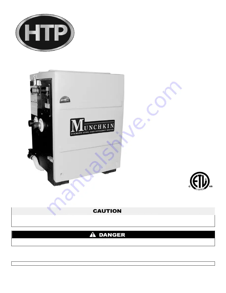
Munchkin
Gas-Fired Boiler
INSTALLATION
START-UP
MAINTENANCE
PARTS
Models
T50M / T80M
80M / 140M / 199M / 399M
Heat Exchanger Bears the “ASME” Stamp
When installing models manufactured after July 7, 2008, you will notice additional selections on the control installer menu that will not
apply to this unit. DO NOT CHANGE THESE FACTORY SETTINGS. Refer to the Control Program Reference Chart within this manual
for selections that apply to this model.
This manual must be used by a qualified installer/service technician. Read all instructions in this manual before installing. Perform steps
in the given order. Failure to comply could result in substantial property damage, severe personal injury, or death.
NOTICE:
HTP reserves the right to make product changes or updates without notice and will not be held liable for typographical errors
in literature.
NOTE TO CONSUMER: PLEASE KEEP ALL INSTRUCTIONS FOR FUTURE REFERENCE.
Summary of Contents for 140M
Page 12: ...12 LP 185 Rev 9 9 14 Figure 1 Dimensions T 50M T 80M 80M ...
Page 13: ...13 LP 185 Rev 9 9 14 Figure 2 Dimensions 140M 199M 399M ...
Page 48: ...48 LP 185 Rev 9 9 14 I DIAGRAMS FOR SIDEWALL VENTING Figure 25 Venting ...
Page 49: ...49 LP 185 Rev 9 9 14 Figure 26 Sidewall Venting ...
Page 50: ...50 LP 185 Rev 9 9 14 J DIAGRAMS FOR VERTICAL VENTING Figure 27 Vertical Venting ...
Page 55: ...55 LP 185 Rev 9 9 14 Figure 29 ...
Page 70: ...70 LP 185 Rev 9 9 14 Figure 31 ...
Page 71: ...71 LP 185 Rev 9 9 14 Figure 32 ...
Page 72: ...72 LP 185 Rev 9 9 14 Figure 33 ...
Page 73: ...73 LP 185 Rev 9 9 14 Figure 34 ...
Page 74: ...74 LP 185 Rev 9 9 14 Figure 35 ...
Page 75: ...75 LP 185 Rev 9 9 14 Figure 36 ...
Page 78: ...78 LP 185 Rev 9 9 14 ...
Page 79: ...79 LP 185 Rev 9 9 14 ...


