


Wi-Fi Thermostat 9000
Colour Touchscreen
Installation Guide
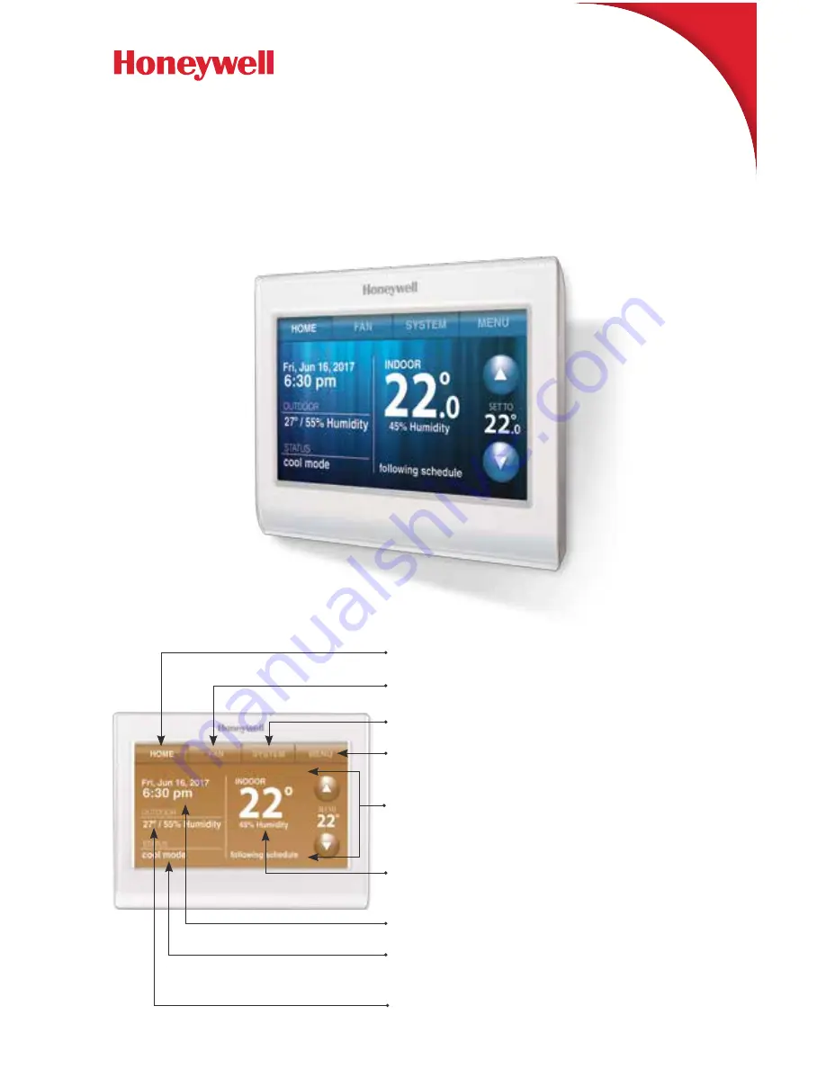
HOME:
Touch to display Home screen.
FAN:
Select fan mode.
SYSTEM:
Select system mode (heat/cool).
MENU:
Touch to display options. Start
here to set a program schedule.
CURRENT SCHEDULE:
Change temperature
setting and select temporary or permanent hold.
INDOOR CONDITIONS:
Shows indoor
temperature and humidity.
CURRENT DATE AND TIME
.
CURRENT STATUS:
Shows system
mode (heat/cool).
OUTDOOR CONDITIONS:
Shows outdoor
temperature and humidity (post registration).


