background image

® U.S. Registered Trademark
Copyright © 2003 Honeywell International Inc.  •  

  • All Rights Reserved 

INSTALLATION INSTRUCTIONS

69-1688

T834C Heating and

Cooling Thermostat

APPLICATION

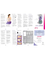
The T834C Thermostat (see Fig. 1) controls 24 to 30 Vac single-stage heating-cooling systems. See Table 1 for 
application information. An spdt mercury switch makes R to W on a temperature fall for heating, and R to Y on a 
temperature rise for cooling.

Fig. 1. T834C internal view.

MERCURY NOTICE

If this control is replacing a control that contains 
mercury in a sealed tube, do not place your old 
control in the trash. Dispose of properly.

Contact your local waste management authority 
for instructions regarding recycling and the 
proper disposal of an old control.

INSTALLATION

When Installing This Product . . .

1.

Read these instructions carefully. Failure to follow 
them could damage the product or cause a hazard-
ous condition.

2.

Check the ratings given in the instructions and on 
the product to make sure the product is suitable for 
your application.

3.

Installer must be a trained, experienced service 
technician.

4.

After installation is complete, check out the product 
operation as provided in these instructions.

Table 1. T834C Specifications.

Model No.

Application

Heat Anticipation

Switching

See Fig. 

No.

System

Fan

T834C

For use in standard heating-
cooling systems.

0.18A to 1.0A, 
adjustable.

Heat-Off-
Cool

On-Auto

2

.18

.2

.25

.3

.5

.7

.9

L

O

N GE R

FAN
SWITCH

TEMPERATURE 
SETTING LEVER

MOUNTING HOLE

SYSTEM
SWITCH

ADJUSTABLE HEAT
ANTICIPATOR
INDICATOR

BIMETAL ELEMENT
BEHIND SCALE

MOUNTING HOLE 
(THERMOSTAT
TO WALL OR
OUTLET BOX)

M21180

69-1688.fm  Page 1  Tuesday, May 6, 2003  10:05 AM

Summary of Contents for T834L1004 - Mercury Free Cool Only Thermostat

Page 1: ...n old control INSTALLATION When Installing This Product 1 Read these instructions carefully Failure to follow them could damage the product or cause a hazard ous condition 2 Check the ratings given in the instructions and on the product to make sure the product is suitable for your application 3 Installer must be a trained experienced service technician 4 After installation is complete check out t...

Page 2: ...rmostat location 3 Set the adjustable heat anticipator indicator to match the current draw of the primary heating control or as recommended by the equipment manufacturer see Heat Anticipator Setting 4 Connect the wires to the terminals on the back of the thermostat See Fig 2 for internal schematic and typical hookup diagram 5 Remove thermostat cover by pulling outward on right edge of cover until ...

Page 3: ...e shown on the nameplate If the current rating is not available proceed as follows to determine the rating 1 Turn off the power 2 Wire the thermostat but do not mount it on the wall 3 Connect the ammeter between the W wire and the W terminal on the thermostat in series with the primary control 4 Prepare the system for operation 5 Turn on the power 6 Turn the System switch to Heat 7 Increase the th...

Page 4: ...the lower end of the temperature scale Place the System switch to the Off position Wait at least five min utes 2 Remove the thermostat cover Move the setting lever until the switch just makes contact The mer cury in the switch rolls to the left end of the tube 3 Replace the cover and wait five minutes for the cover and the thermostat to lose the heat it has gained from your hands If the thermomete...

Reviews: