Honeywell Searchline Excel, Technical Handbook
The Honeywell Searchline Excel is a cutting-edge gas detection system, ensuring the utmost safety in any environment. Experience seamless installation with the comprehensive Installation Manual provided for free download on our website. Equip your facility with this state-of-the-art product and access the manual at manualshive.com to optimize operations and safeguard lives.
Share
Download


Reviews:
No comments
Related manuals for Searchline Excel

1501-0581
Brand: Raptor Series Pages: 2

BX1508
Brand: Blue Ox Pages: 3

RM2551
Brand: Dometic Pages: 52
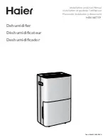
HEN70ETFP
Brand: Haier Pages: 36

CXW-219-D69
Brand: Haier Pages: 13
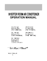
H2SM-21HX03
Brand: Haier Pages: 27

HRFZ-250D AA
Brand: Haier Pages: 104

TPS-FPAR2000L
Brand: Crestron Pages: 2

200057
Brand: Bartscher Pages: 72

13133
Brand: SAN-UP Pages: 2

MCP110
Brand: Ikegami Pages: 2

NSX-BL13
Brand: Aiwa Pages: 18

2733
Brand: Geuther Pages: 8

lake
Brand: Noro Pages: 16

OPW 12VW-AV Series
Brand: Dover Pages: 16

310-136
Brand: Airaid Pages: 2

play sphere 90
Brand: Jacuzzi Pages: 40

STAR Euro 5
Brand: Karsan Pages: 104


