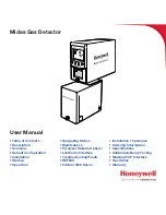
background image

Midas Gas Detector

User Manual

• 

Table of Contents

• 

Description

• 

Overview

• 

Default Configuration

• 

Installation

• 

Startup

• 

Operation

• 

Navigating Menus

• 

Maintenance

• 

Pyrolyzer Module Options

• 

LonWorks Interface

• 

Troubleshooting/Faults

• 

REFLEX

• 

Internal Web Server

• 

Installation Topologies

• 

Ordering Information

• 

Specifications

• 

Calibration/Bump Testing

• 

Modbus/TCP Interface

• 

Gas Tables

• 

Warranty

Summary of Contents for Midas

Page 1: ...ration Installation Startup Operation Navigating Menus Maintenance Pyrolyzer Module Options LonWorks Interface Troubleshooting Faults REFLEX Internal Web Server Installation Topologies Ordering Information Specifications Calibration Bump Testing Modbus TCP Interface Gas Tables Warranty ...

Page 2: ...ensor Cartridge 2 4 2 3 1 Biased Sensor Cartridges 2 4 2 4 Cover 2 5 3 Default Configuration 3 2 4 Installation 4 2 4 1 Mounting and Location of Detector 4 2 4 2 Mechanical Installation 4 4 4 3 Sample and Exhaust Tubing Calculations 4 7 4 5 Local Detector Option 4 8 4 6 Electrical Installation 4 8 4 7 Electrical Connections 4 11 4 8 Refitting the Main Chassis 4 23 4 9 Installing the Sensor Cartrid...

Page 3: ...eview Software 7 2 7 1 2 Review Alarms 7 3 7 1 3 Review 4 20 mA Output 7 3 7 1 4 Review Faults 7 3 7 1 5 Review Calibration 7 4 7 1 6 Review Date and Time 7 4 7 1 7 Review Detector Address 7 5 7 1 8 Review Event Log 7 5 7 1 9 Review LCD Backlight Mode 7 6 7 2 Set up Calibration and Test Modes 7 6 7 2 1 Set up Menu 7 7 7 2 2 Set Alarms 7 7 7 2 3 Set 4 20 mA output 7 9 7 2 4 Set Faults 7 9 7 2 5 Set...

Page 4: ...2 Pump Replacement 8 4 8 3 Reassembling the Detector 8 6 8 4 Filter Replacement 8 6 8 5 System Leak Check Procedure 8 7 9 Pyrolyzer Module Options 9 2 9 1 Fitting the Pyrolyzer Module 9 4 9 2 Reassembling the Detector 9 6 9 3 Configuring the Detector 9 7 10 Midas LonWorks Interface Module 10 2 10 1 LonWorks Installation 10 2 10 1 1 Fitting the LonWorks Module 10 2 10 1 2 Wiring the Midas for LonWo...

Page 5: ...ion 14 2 14 2 Modbus TCP Installation 14 3 14 3 Power over Ethernet PoE Installation 14 3 15 Ordering information 15 2 15 5 Midas Complete Gas Detector Kits 15 3 15 6 Accessories and Spares 15 4 16 Specifications 16 2 17 Calibration and Bump Testing 17 2 A Modbus TCP Interface A 2 A 1 Reading Status from the Midas A 2 A 2 Sending Commands to the Midas A 6 A 3 Determining the MAC Address A 7 B Gas ...

Page 6: ...ral industrial or domestic waste This product should be disposed of through suitable WEEE disposal facilities For more information about disposal of this product contact your local authority distributor or the manufacturer EU Directive 2012 19 EU Waste Electrical and Electronic Equipment WEEE ...

Page 7: ...Midas Gas Detector 1 1 1 Description ...

Page 8: ...ounted and displays gas concentration alarm fault and status information via its backlit LCD and LEDs A simple to use 4 button keypad located under the display provides the facility to set up review operate and make changes to the detector s configuration Midas has flexible power and communications capabilities built in as standard These include 3 on board relays 0 21 mA analog output Modbus TCP o...

Page 9: ...Midas Gas Detector 2 1 2 Overview ...

Page 10: ...sis Display Sensor cartridge chamber Pump module Service Port Caution The Service Port is only for use with approved connectors by Honeywell Analytics service personnel operating a system diagnostic Unauthorized connection to this port may lead to damage of the Midas and external equipment and will not be covered by the normal product warranty conditions 2 1 1 Display The display is located at the...

Page 11: ...nnection between the sensor cartridge and the rest of the electronics as well as providing the chamber where the sensor cartridge is exposed to the sampled gas This connection is lightly lubricated for ease of sensor replacement Avoid contact of sensor cartridge chamber with contaminants such as dust and debris For details of fitting sensor cartridge refer to Section 4 9 2 2 Mounting Bracket Assem...

Page 12: ...bs Some cartridges are shipped with a protective cap to shield them from contaminants during shipping This cap must be removed before inserting the cartridge into the Midas unit failure to do so may damage the Midas transmitter Diagram 2 5 Sensor cartridge REMOVE AT TIME OF INSTALLATION Front Back Connector Locking tabs Protective Cap remove before use 2 3 1 Biased Sensor Cartridges Some sensor ca...

Page 13: ...are the 4 push buttons used for navigating the detector s software menus The cover is easily removed to allow access to the chassis by unscrewing the thumbscrew on the front panel and pulling the cover forwards off the main chassis Midas units fitted with a pyrolyzer utilize a ventilated cover due to the high temperatures generated by the pyrolyzer unit See Diagram 2 7 Diagram 2 7 Midas covers LED...

Page 14: ...Midas Gas Detector 3 1 3 Default Configuration ...

Page 15: ...fault 19 5 v v In that case Honeywell Analytics recommends one of the following Use Modbus TCP digital communications Use discrete relay inputs instead of a 4 20 mA signal to trigger gas alarms Program the control system of the 4 20 mA input with logic and a delay e g 1 second before triggering an alarm to determine if the 4 20 mA output is at one of the 0 4 mA conditions described above Contact H...

Page 16: ...es on alarm Contact Normally Open NO closes on alarm Alarm 2 Relay 2 TLV 20 LEL 19 5 v v Falling Normally de energized energizes on alarm Contact Normally Open NO closes on alarm Fault Relay 3 Normally energized de energizes on fault Contact Normally Open NO Instrument Fault Only Latching Latching Alarm and fault relays DO NOT automatically reset when reading falls below alarm thresholds Relays MU...

Page 17: ...Midas Gas Detector 4 1 4 Installation ...

Page 18: ...llation ensure local regulations and site procedures are followed Diagram 4 1 Midas outline dimensions zellweger analytics z GAS DETECTOR 5 91 in 150 00mm 4 72 in 120 00mm 2 48 in 63 00 honeywell honeywell MDA Scientific Midas PN MIDAS E CDX SN 12K 48397 Activate by 24 Nov 12 4 1 Mounting and Location of Detector The Midas gas detector has an integral mounting bracket assembly that is easily mount...

Page 19: ...in 140 mm 4 4 in 113 mm 9 1 in 233 mm 2 3 in 59 mm MIDAS T HTP Note Heat shield not present on all pyrolyzers 3 9 in 205 mm 3 9 in 98 mm 2 4 in 60 mm 5 2 in 132 mm 9 6 in 244 mm Midas T 00P MIDAS A 103 honeywell honeywell MDA Scientific Midas PN MIDAS E CDX SN 12K 48397 Activate by 24 Nov 12 MIDAS T 0P3 MIDAS A 039 MIDAS T NP1 LQ PP LQ PP LQ PP LQ PP LQ PP ...

Page 20: ...r the inlet filter for local monitoring 10 Take into consideration the space required for cable or conduit access 4 2 Mechanical Installation The following steps and diagrams show how to separate the mounting bracket assembly from the main chassis and mount it on a vertical flat surface 1 Unscrew the thumbscrew located on the front panel 2 Remove the cover by pulling it forwards off the main chass...

Page 21: ...NOTICE Remove internal shipping protection from the pump module brfore installation Removing chassis mounting bracket chassis IMPORTANT NOTICE Remove internal shipping protection from the pump module brfore installation Internal packing card Remove before use Internal packing card Remove before use Chassis Mounting Screws ...

Page 22: ...Mount Optional Midas Adjustable L Bracket Mount mounting bracket screws Standard Midas Wall Mount Diagram 4 3 Mechanical installation Note When using theAdjustable L bracket with the High Temperature Pyrolyzer unit 2 TopAccessTubing Connectors MIDAS A 031 must be used to insure proper operation Top Access Tubing Connector MIDAS A 031 honeywell honeywell MDA Scientific Midas PN MIDAS E CDX SN 12K 4...

Page 23: ... Maximum Tubing OD mm in 6 35 0 25 Tubing ID mm in 4 76 0 188 Note HoneywellAnalytics recommends the use of Teflon FEP Fluorinated Ethylene Polymer tubing to assure proper sample transport The properties of Teflon FEP make it the best choice for transporting sample toxic gases to instruments when compared with the properties of other similar tubing materials If the pressure vacuum on the inlet exh...

Page 24: ... a remote location Diagram 4 4 Local gas detector option MIDAS T 001 transmitter installed with in line particulate filter for local ambient monitoring mode 4 6 Electrical Installation Access for the electrical wires to the terminal module is made via the PG16 cable gland located at the bottom of the mounting bracket assembly The cable gland can be removed and replaced with a suitable conduit fitt...

Page 25: ...Diagram 4 5 shows the terminal module layout and terminal identification as well as the jumper locations Note Earthing Requirements If the Midas unit s metal chassis is not connected directly to a metal surface for earthing purposes an additional earth wire will be required Connect a wire via the PG16 gland to the dedicated earth tag screw terminal located on the bottom bracket and connect the oth...

Page 26: ...trolled remotely from a separate controller system using Modbus TCP commands or via LonWorks if the optional interface is used In this remote mode the relays cannot be controlled by the Midas itself and only by the remote controller device PLC SCADA etc Display Description Relay 1 Relay 2 Relay 3 1FLt Instrument Fault Only Alarm 1 Alarm 2 Instrument Fault 2Flt Separate Fault Relays Any Alarm Maint...

Page 27: ...DAS Simplified Internal Schematic 2 1 Ethernet 24 VDC R Load RJ 45 Connector 48 VDC 4 7 Electrical Connections Midas can be powered by either 24 VDC via traditional discrete wiring or by approximately 48 VDC delivered through the Ethernet cable from a PoE source In either case the 4 20 mA analog output can be used This can be configured for fully isolated operation With 24 VDC power the 4 20 mA ou...

Page 28: ...5701 A 0330 System 57 Relay Field Interface Card 5701 Control Card 24 VDC 35 36 29 28 24 VDC Sense Resistor Cabinet 29 35 28 36 Shielded Cable Isolated Loop Supply 40 mA max Transmitter Supply 5701 Card Sensor Drive Module Link Positions LK12 LK5 LK6 LK7 LK8 LK9 LK10 LK11 LK1 LK2 LK3 LK4 LK13 RJ 45 8 7 2 3 4 5 6 1 DC PWR 24 V COM NO NC Relay3 Relay2 Relay1 ON SW OFF 11 10 9 Analog Current Loop 4 2...

Page 29: ...terface Card 5701 Control Card 24 VDC 27 29 28 Sense Resistor 170 Ohm Cabinet 29 28 27 Shielded Cable Transmitter Supply 5701 Card Sensor Drive Module Link Positions LK12 LK5 LK6 LK7 LK8 LK9 LK10 LK11 LK1 LK2 LK3 LK4 LK13 RJ 45 8 7 2 3 4 5 6 1 DC PWR 24 V COM NO NC Relay3 Relay2 Relay1 ON SW OFF 11 10 9 Analog Current Loop 4 20 mA INT EXT EXT INT supply J5 J4 supply J1 NO NC J2 NO NC J3 PYROLYZER ...

Page 30: ...terface Card 5701 Control Card 24 VDC 27 29 28 Sense Resistor 170 ohm Cabinet 29 28 27 Shielded Cable Transmitter Supply 5701 Card Sensor Drive Module Link Positions LK12 LK5 LK6 LK7 LK8 LK9 LK10 LK11 LK1 LK2 LK3 LK4 LK13 RJ 45 8 7 2 3 4 5 6 1 DC PWR 24 V COM NO NC Relay3 Relay2 Relay1 ON SW OFF 11 10 9 Analog Current Loop 4 20 mA INT EXT EXT INT supply J5 J4 supply J1 NO NC J2 NO NC J3 PYROLYZER ...

Page 31: ...J5 J4 supply J1 NO NC J2 NO NC J3 PYROLYZER CONNECTOR Relay1 Relay2 Relay3 24 VDC 24 VDC Note The above schematic shows the MIDAS connected to channel 1 on the 5704 card The terminal numbers for all four channels are as follows MIDAS Function Loop Loop Midas Terminal Number Color in this figure 5704 Channel 1 Terminal 5704 Channel 4 Terminal 5704 Channel 3 Terminal 5704 Channel 2 Terminal 11 Brown...

Page 32: ...ly J1 NO NC J2 NO NC J3 PYROLYZER CONNECTOR Relay1 Relay2 Relay3 Sieger System 57 Quad Relay Interface Card 05704 A 0121 with 4 Channel Control Card 05704 A 0145 24 VDC 24 VDC Note The above schematic shows the MIDAS connected to channel 1 on the 5704 card The terminal numbers for all four channels are as follows MIDAS Function Analog Out Common Midas Terminal Number Color in this figure 5704 Chan...

Page 33: ...1 touchpoint1 Simplified Internal Schematic 1 3 2 24 VDC signal 24 VDC External Customer Provided Power Supply touchpoint 1 RJ 45 8 7 2 3 4 5 6 1 DC PWR 24 V COM NO NC Relay3 Relay2 Relay1 ON SW OFF 11 10 9 Analog Current Loop 4 20 mA INT EXT EXT INT supply J5 J4 supply J1 NO NC J2 NO NC J3 PYROLYZER CONNECTOR Relay1 Relay2 Relay3 Diagram 4 16 Midas to Touchpoint1 4 Wire Connection ...

Page 34: ...hpoint 1 Shielded Cable touchpoint1 Simplified Internal Schematic 1 3 2 24 VDC signal RJ 45 8 7 2 3 4 5 6 1 DC PWR 24 V COM NO NC Relay3 Relay2 Relay1 ON SW OFF 11 10 9 Analog Current Loop 4 20 mA INT EXT EXT INT supply J5 J4 supply J1 NO NC J2 NO NC J3 PYROLYZER CONNECTOR Relay1 Relay2 Relay3 Diagram 4 17 Midas to Touchpoint1 3 Wire Sourcing Connection ...

Page 35: ... Loop 4 20 mA INT EXT EXT INT supply J5 J4 supply J1 NO NC J2 NO NC J3 PYROLYZER CONNECTOR Relay1 Relay2 Relay3 HA71 Analog Input Card R2 R1 ANALOG INPUTS R3 R4 R7 R6 R5 EXC DC PWR TB2 R8 JP1 ST 71 ANALOG INPUT BOARD 0010 1115 ASSY 10 0158 J2 J1 CH1 9 EXC HI CH7 15 HI EXC CH3 11 EXC LO HI LO CH5 13 LO HI EXC LO CH2 10 HI EXC CH8 16 CH4 12 EXC LO HI C X E O L CH6 14 EXC LO O L I H HI 3 Wire 4 20mA ...

Page 36: ...ly J1 NO NC J2 NO NC J3 PYROLYZER CONNECTOR Relay1 Relay2 Relay3 24 VDC HI EXC 24 VDC Sense Resistor Loop Supply Not optically isolated HA71 Analog Input Card R2 R1 ANALOG INPUTS R3 R4 R7 R6 R5 EXC DC PWR TB2 R8 JP1 ST 71 ANALOG INPUT BOARD 0010 1115 ASSY 10 0158 J2 J1 CH1 9 EXC HI CH7 15 HI EXC CH3 11 EXC LO HI LO CH5 13 LO HI EXC LO CH2 10 HI EXC CH8 16 CH4 12 EXC LO HI C X E O L CH6 14 EXC LO O...

Page 37: ...INT EXT J5 EXT INT 11 10 9 MIDAS Simplified Internal Schematic 2 1 touchpoint4 Simplified Internal Schematic 1 3 2 24 VDC signal 24 VDC External Customer Provided Power Supply RJ 45 8 7 2 3 4 5 6 1 DC PWR 24 V COM NO NC Relay3 Relay2 Relay1 ON SW OFF 11 10 9 Analog Current Loop 4 20 mA INT EXT EXT INT supply J5 J4 supply J1 NO NC J2 NO NC J3 PYROLYZER CONNECTOR Relay1 Relay2 Relay3 ...

Page 38: ...J4 INT EXT J5 EXT INT 11 10 9 MIDAS Simplified Internal Schematic 2 1 touchpoint4 Simplified Internal Schematic 1 3 2 24 VDC signal Shielded Cable RJ 45 8 7 2 3 4 5 6 1 DC PWR 24 V COM NO NC Relay3 Relay2 Relay1 ON SW OFF 11 10 9 Analog Current Loop 4 20 mA INT EXT EXT INT supply J5 J4 supply J1 NO NC J2 NO NC J3 PYROLYZER CONNECTOR Relay1 Relay2 Relay3 ...

Page 39: ...DAMAGE 5 Align the two attaching screws located at the bottom of the chassis with the screw threads on the mounting bracket assembly 6 Tighten the screws to secure the chassis to the mounting bracket assembly Diagram 4 20 Refitting the chassis PCB CONNECTOR TUBES 4 9 Installing the Sensor Cartridge The Midas sensor cartridge is supplied separately and needs to be fitted to the detector s main chas...

Page 40: ...aligning the slots on either side with the locating tabs on the mounting bracket assembly 9 Push the cover horizontally until fully seated 10 Tighten the thumbscrew on the front panel Diagram 4 21 Installing the sensor cartridge chassis cartridge slots tighten How cover is fitted tabs cartridge fitted midas Gas Sensor Cartr idge NITROGEN TRIFLUORIDE NF3 PN MIDAS S HFX SN 0234456670 Use by 07 09 20...

Page 41: ...Midas Gas Detector 5 1 5 Startup ...

Page 42: ...e as shown in Section 6 6 Perform a leak test as shown in Section 8 5 to ensure all connections are secure 6 If using a multi gas sensor cartridge refer to Section 7 2 2 to ensure the correct gas ID code is selected 7 Allow the detector to stabilize until the WArm message is no longer displayed The maximum warm up time is listed in Appendix B Warm up times are typically much faster 8 If this is a ...

Page 43: ...Midas Gas Detector 6 1 6 Operation ...

Page 44: ...or calibration process or a user requested inhibit the display will flash For details of fault and maintenance fault codes refer to Section 11 Note The first time the Midas is started with a new sensor cartridge an F49 or F88 fault code may be displayed there is no actual fault and the fault message can be cleared by depressing the X cancel button for two seconds Final Start Up Routine Screen Norm...

Page 45: ...te flash Greater than full scale Alarm relay 1 activated Alarm relay 2 activated Fault relay activated 21 mA Green flash Red flash Green White flash Yellow flash Inhibit Alarm relay 1 de activated Alarm relay 2 de activated Fault relay activated 2 mA Green flash Green Green Low flow rate Alarm relay 1 de activated Alarm relay 2 de activated Fault relay activated 3 mA Green flash Yellow on Green Ye...

Page 46: ... clear when the fault condition is cleared 6 2 Review Mode The detector settings can be reviewed safely without thepossibilitytomakechangesbyusingreviewmode To select review mode press the s up or t down button once The review mode icon will show on the display and the first review mode menu icon is displayed 6 2 1 Review Mode Menu Overview The menu is simply navigated by using the s up and t down...

Page 47: ...e Year of last calibration Month and day of last calibration Date Time tImE Year Month Day Time Address nEt Shows web access level Use DHCP server for IP parameters IP address byte 1 IP address byte 2 IP address byte 3 IP address byte 4 Subnet mask byte 1 Subnet mask byte 2 Subnet mask byte 3 Subnet mask byte 4 Event Log hiSt Date of latest event Time of latest event Description of latest event Da...

Page 48: ...our local Honeywell Analytics service department After successfully entering the pass code if set the first menu SET set up icon will show on the display The CAL calibration or tESt test menu can alsobeselected using the s upor t down buttons Press the 3 accept button to enter the selected menu or the X cancel button to return to normal operation mode 6 3 1 Set up Menu Overview The set up menu all...

Page 49: ... or mm dd Set year yyyy 2003 2030 Set month mm 01 12 Set Day dd 01 31 Set hour hh 00 23 Set minute mm 00 59 Address nEt Set Web Access WA Y full access WA n read only Set Auto or Manual address AU Y DHCP AU n man Manual IP address byte 1 Manual IP address byte 2 Manual IP address byte 3 Manual IP address byte 4 Manual Subnet mask byte 1 Manual Subnet mask byte 2 Manual Subnet mask byte 3 Manual Su...

Page 50: ...e any changes to a selected setting and are confirmed using the 3 accept button The X cancel button can be used to exit the submenu and allow selection of a different submenu or can be pressed again to exit to the main set up calibration and test menu Pressing the X cancel button again returns the detector to normal operating mode The table below shows an overview of the calibration submenus and h...

Page 51: ...ange is 0 min to 99 min Default is 3 min Remaining purging time in second is displayed Select inhibit state after exiting cal menu Inh Y set full inhibit Inh n keep initial inhibit state Set inhibit timeout Set range is 00 hour 00 minute to 4 00 Default is 30 minutes Flow FLoW Icon flashes display shows 0 indicating flow zero will be set Unit counts down from 10 to 0 and sets flow zero Display sho...

Page 52: ... guidelines for recommended best practices Bump test concentrations recommended in Appendix B are calculated to generate a minimum first alarm level response Table 6 5 Test Submenu Display Screen 1 Screen 2 Screen 3 Screen 4 Bump bUmP Apply bump test gas and display shows measured gas concentration with all alarm outputs inhibited Press X to exit to test menu Alarm fault SIm Display shows Sim and ...

Page 53: ...Midas Gas Detector 7 1 7 Navigating Modes and Submenus ...

Page 54: ...Calibration Days left to next calibration due and date of last calibration Time Date tImE Current year date and time IP address Auto address selection on off IP address sub net mask values Event log View the date time and details of the last seven alarm fault and maintenance fault events LCD LCD LCD backlight mode To select review mode from normal operation press the s up or t down button once The...

Page 55: ...submenu 12 Press X to return to normal operation 7 1 3 Review 4 20 mA Output mA 1 Select the 4 20mA mA submenu and press 3 to accept 4 mA will be displayed 2 Press 3 to display the gas conc corresponding to 4 mA 20 mA will be displayed 3 Press 3 to display the gas conc corresponding to 20 mA 4 Press 3 to return to step 1 5 Repeat steps 1 through 5 to view the settings again or press s up or t down...

Page 56: ...h and day of the last calibration 5 Press 3 to return to step 1 6 Repeat steps 1 through 4 to view the settings again or press s up or t down to select another submenu 7 Press X to return to normal operation 7 1 6 Review Date and Time timE Select the review date and time timE submenu and press 3 to accept 1 The current year setting is displayed 2 Press 3 to display the current month and day 3 Pres...

Page 57: ...es will be displayed preceded by the letter n 9 Press 3 to scroll through the second third and forth sub net values The number of dots in the upper left indicate which part of the sub net address is being viewed 10 Press 3 to return to step 1 11 Repeat steps 1 through 9 to view the settings again or press s up or t down to select another submenu 12 Press X to return to normal operation 7 1 8 Revie...

Page 58: ...bration test function if no button is pressed for 5 minutes or if an alarm level is exceeded PASS CODE If a pass code has been set the display will show 0000 with the first 0 flashing Use the s up or t down buttons to set the first digit of the pass code Press 3 to enter the first digit The second digit will then flash Repeat the process until all four pass code digits have been entered If an inco...

Page 59: ...ges and is indicated by displaying UPdt on the LCD If however the X cancel button is pressed at any time before the changes are accepted this will cause any changes to be cancelled in that particular submenu To select the set up menu from normal operation press the s up button for a few seconds Enter the pass code if set Use the s up or t down buttons to select the set up menu icon and press the 3...

Page 60: ...19 Use the s up or t down buttons to change between the settings 20 Press 3 to update all the changes UPdt displayed and return to step 1 21 Press s up or t down to select another submenu 22 Press X to return to set up calibration and test menu selection 23 Press X again to return to normal operation Note When replacing a single gas sensor cartridge withthesametypesinglegassensorcartridge no chang...

Page 61: ...yed 3 Use the s up or t down buttons t o c h a n g e t h e c o n f i g u r a t i o n See Table 7 3 for details of fault relay configurations 4 Press 3 to display the flashing fault output latching L or non latching nL setting is displayed 5 Use the s up or t down buttons to change between the settings 6 Press 3 to display the flashing fault output normally energized nE or normally de energized nd ...

Page 62: ...erval CAL submenu and press 3 to accept 2 The flashing display shows the number of days interval after a calibration that a calibration due maintenance fault will be displayed 3 Use the s up or t down buttons to change the number of days If the calibration interval is set below 001 then OFF will be displayed and no user calibration interval will be activated and no reminders displayed 4 Press 3 to...

Page 63: ...Interface Module the default IP address must be used 1 Select the set address nEt submenu and press 3 to accept 2 Press s up or t down to select full web access WA Y or read only WA n and press 3 to accept 3 A flashing n or Y is displayed depending on if auto address detection is on AU Y or off AU n 4 If automatic address detection AU Y is selected then the detector will automatically appoint a va...

Page 64: ...nd value 4 Press s up or t down to set the second value 5 Press 3 to enter and repeat for the third and forth values in the passcode 6 To confirm the pass code re enter it again using the same procedure 7 The new pass code will be saved after the last entry if the two entered passcodes are the same Note Pass codes can be set between 0001 and 9999 Setting the pass code to 0000 will switch off the p...

Page 65: ...s Geration 2 software versions include automatic pump frequency detection Manual setting of pump control frequency is uncommon and is needed only if pump frequency differs significantly from the expected range 7 2 10 Set Pump control frequency 1 Select the set Pump Control Frequency PUmP submenu and press 3 to accept 2 The flashing Pump Control Frequency configuration is displayed 3 Use the s up o...

Page 66: ...gas 3 The inhibit icon is also displayed indicating that no alarm outputs will be generated during this process 4 For CO2 calibrations apply CO2 free air for three minutes 5 Press 3 to confirm when ready and the icon goes steady 6 For non CO2 calibrations apply the zero gas or ambient air 7 The dots on the left of the display indicate progress to a successful zero 8 The display will show the zero ...

Page 67: ...process 4 Use the s up or t down buttons to select the gas ID code of calibration gas for multi gas ID sensor cartridges only and press 3 to accept Refer to Appendix B for details of gas ID codes 5 Use the s up or t down buttons to select if humidified HUm or dry drY calibration gas is being used 6 Use the s up or t down buttons to change the value to the concentration of span calibration gas bein...

Page 68: ...as hour minute Default value is 30 minutes 00 30 24 Press 3 to accept inhibit settings Updt will be displayed 25 The selected outputs will be inhibited until the inhibit timeout has elapsed Note If the inhibit timeout elapses before the inhibit state is set back to nonE maintenance fault code M17 will be displayed Note The change in the gas bottle icon s contents gives an indication of the relativ...

Page 69: ...flashes 8 Press s up or t down to enter the actual value read on the external flow meter NOTE Holding down the button will increase the increment speed 9 Press 3 to confirm and the icon goes steady and a count down from 10 is shown as the setpoint 1 value is read 10 Thedisplaywillshowtheflashingflowiconwiththe dot 3 4 ways up to tell the user to set the set point 2 flow 650 cc min 11 Press s up or...

Page 70: ...calibration and test menu selection 9 Press X again to return to normal operation 7 4 Test Menu tESt The test menu is used to test the detector gas reading using bump test gas and for simulation of alarm and fault display and output operation relay analog and digital The test submenu also includes the detector inhibit facility The test menu comprises of 3 submenus as shown in the table below Cauti...

Page 71: ... Section 17 are calculated to generate a minimum first alarm level response 7 4 2 Alarm Fault Test SIm 1 Use the s up or t down buttons to select the alarm fault test SIm submenu and press 3 to accept 2 The display shows SIm and the A1 s icon 3 Use the s up or t down buttons to select A1 s A2 or Fault for test simulation A steady indicates an m9 simulated fault and a flashing is an F39 simulated f...

Page 72: ...ance fault code M17 will be displayed 8 To take the unit out of inhibit select the inhibit InH submenu and press 3 to accept 9 Use the s up or t down buttons to select nonE 10 Press 3 to return to the submenu selection 11 Press s up or t down to select another submenu 12 Press X to return to set up calibration and test menu selection 13 Press X again to return to normal operation Table 7 8 Inhibit...

Page 73: ...ease or decrease current as desired in the range of 1 to 21 mA Displayed as S xx xx indicating mA current being output 4 Press X to return to the 4 20 submenu selection 5 Press X to return to set up calibration and test menu selection 6 Press X again to return to normal operation Caution Proceeding with 20 mA stimulation may cause unexpected alarm activation Only authorized operators should perfor...

Page 74: ...Midas Gas Detector 8 1 8 Maintenance ...

Page 75: ...nt methods or operating conditions can actually damage the sensor cartridge s lifetime and alter the calibration adversely Only qualified calibration technicians should attempt to calibrate the Midas gas detector Note For details regarding sensor cartridge calibration and bump testing method refer to Section 17 The internal pump module is designed to operate for a minimum of 24 months and it is re...

Page 76: ... of the sensor cartridge see diagram 24 6 Switch the power switch on the terminal module to the on position 7 Refit the detector s cover by aligning the slots either side with the locating tabs on the mounting bracket assembly and pushing the cover horizontally until home Tighten the thumbscrew located on the front panel see diagram 25 8 Confirm that the LCD messages LOAd and WArm are replaced by ...

Page 77: ...has been designed to allow easy replacement New pump modules MIDAS A 007 are supplied with new springs bracket and tubing pre assembled for quick release replacement Diagram 8 5 Location of pump module Pump module MIDAS A 007 The following procedure should be followed carefully and only performed by suitably trained personnel 1 Isolate the power to the detector 2 Unscrew the thumbscrew located on ...

Page 78: ...ubes at the manifold 8 Slide the pump module out and disconnect the connector from the pcb 9 Fit the new pump module following the steps above in reverse order Orient the metal retaining clamps away from the pump wiring to prevent damage Route pump wiring away from the chassis and manifold to prevent damage ...

Page 79: ... module to the on position 8 Refit the detector s cover by aligning the slots either side with the locating tabs on the mounting bracket assembly 9 Push the cover horizontally until home 10 Tighten the thumbscrew located on the front panel Note Honeywell Analytics recommends conducting a Flow Calibration See Section 7 3 for instructions 8 4 Filter Replacement The internal filter MIDAS A 009 has be...

Page 80: ...ines Example O2 oxygen plugging of the ports causes the O2 levels within the Midas flow path to be depleted as the sample becomes stagnant The result is the concentration levels begin to fall and trigger the alarms for the O2 depletion 1 Place the Midas into Inhibit see Section 7 4 3 2 Plug the Inlet Sample line see Diagram 8 8 3 The flow meter indicators will begin to drop and ultimately disappea...

Page 81: ... time to fault is 1 minute 10 Remove the plug 11 Allow 15 seconds or so to allow the Midas flow and concentrations to stabilize then clear the fault by pressing and holding X 12 Return the unit to normal operation Diagram 8 8 Port Location Gas outlet port Gas inlet port ...

Page 82: ...Midas Gas Detector 9 1 9 Pyrolyzer Module Options ...

Page 83: ...NP1 detects nitrogen triflouride NF3 and Perfluoro compounds CH3F C4F6 C5F8 CH2F2 The pyrolyzer unit for NF3 CH3F and CH2F2 can utilize a Freon end of line filter P N 1830 0027 The filter is filled with charcoal to remove Freon and other similar compounds from the sample gas before it is cracked in the pyrolyzer Diagram 9 1 illustrates the various pyrolyzer configurations This table shows that gas...

Page 84: ... inadéquate pourrait causé des blessures ainsi que des dommages à l appareil Diagram 9 2 shows the main components of the pyrolyzer Diagram 9 2 Pyrolyzer components Diagram 9 2 Pyrolyzer components Diagram 9 3 shows in a simple form how a gas sample is drawn through the pyrolyzer module by the pump located at the end of the gas path It is first routed to the pyrolyzer via the Freon filter before b...

Page 85: ...rews located at the bottom front of the chassis 5 Pull the chassis forward to disconnect it from the mounting bracket assembly see Diagram 9 5 Diagram 9 5 Removing the chassis mounting bracket chassis 6 Thread the connector and wire harness from the pyrolyzer through the rectangular access in the bottom of the mounting bracket 7 Secure the wires with a retention clip if available 8 Plug the connec...

Page 86: ... may require more frequent bump testing or calibration to confirm working specification Because of the higher operat ing temperatures when using the pyrolyzer module Honeywell Analytics strongly recommends that the ventilated Midas Top Cover shown in Diagram 9 1 be used in all pyrolyzer applications Note Consult the label on the side of the Pyrolyzer module as shown in Diagram 9 7 for the firmware...

Page 87: ...TION The LCD is fragile Do not apply pressure to its surface 3 Tighten the retaining screws to secure the chassis to the mounting bracket 4 Insert the MIDAS S XHF sensor cartridge into the sensor cartridge chamber see Diagram 9 8 and refer to the Sensor Cartridge Installation Quick Start Guide MIDAS A 021 Diagram 9 8 Reassembling the detector cartridge chassis 5 Set the power switch to the on posi...

Page 88: ...the gas ID number to that of the target gas Press P to accept 7 Continue to accept or change the rest of the alarm settings For further details on these settings refer to the Midas Operating Instructions part number MIDAS A 001 8 Press P to update all changes UPdt will be displayed 9 Press X twice to return to normal operation After applying power verify that the sensor cartridge ID and gas ID are...

Page 89: ...Midas Gas Detector 10 1 10 Optional LonWorks Interface Installation ...

Page 90: ... Midas to LonWorks Interface Cable MIDAS A 040 10 1 1 Fitting the LonWorks Module 1 Unscrew LonWorks interface top plate 2 Mount the interface and tighten screws See mounting template on reverse side 3 Connect 24V DC power and LonWorks wires to the pluggable connectors Clamp the cables in the supplied gland as shown in Diagram 10 2 A spare gland is included 4 Reinstall top plate on the interface 5...

Page 91: ...g2 Care must be taken when inserting plug to assure correct alignment 4 Plug1 and Plug2 are internally connected in parallel to facilitate wiring in bus topology 5 LonWorks FT 10 wiring is polarity sensitive Lon A and Lon B may be swapped 10 1 3 Configuring the Midas for LonWorks 1 Turn on 24 VDC power 2 Confirm that the Midas initiates the power up sequence 3 Reset Fault F49 if present 4 Set alar...

Page 92: ...is shown in Diagram 10 3 Information on LonWorks can be found at www echelon com Information on LonMark can be found at www lonmark org Many commercial LonWorks compatible products can be found at www engenuity com Diagram 10 3 LonMark Diagram MIDAS LonWorks Gateway Device Open loop sensor Functional Block nviReset SNVT_lev_disc nvoConc SNVT_ppm_f nv1 nvoFaultD SNVT_lev_disc nvoFaultS SNVT_switch ...

Page 93: ...ifferent than that of other Honeywell Analytics MDA Scientific gas detectors For example a Vertex will indicate a level 1 alarm by ST_MED This is because ST_LOW is reserved for small non zero concentrations below the alarm threshold Additionally the System 16 LIFELINE LIFELINE II and CM4 indicate a level 2 alarm as ST_MED Table 10 1 Alarm Outputs Alarm Status nvoAlmL SNVT_lev_ disc nvoAlm2 SNVT_le...

Page 94: ...generally be issued 30 days before F43 However this variable provides no advance warning of fault m11 User Cal Expired nvoMonState The bits in this variable are shown graphically in Table 10 2 The least significant 4 bits form a monitoring mode integer MMI Bit 7 2 form a heartbeat counter which increments every 2 seconds The heartbeat counter is provided to facilitate confirmation of communication...

Page 95: ...onds The effective value is clamped to 180 seconds and 5 seconds regardless of the programmed value Additionally every NVO will repropagate when the status of its function block changes and nciMinSendT has expired since the last propagation This has a default value of 5 seconds The effective value is clamped to 10 seconds and 1 second nviRelay1 nviRelay2 and nviRelay3 These network variable inputs...

Page 96: ...equipment should be designed to prevent creation of expensive or dangerous conditions when the relays de energize For applications requiring a highly reliable digital output Honeywell Analytics recommends purchasing a dedicated DO device nviReset This network variable input causes alarms and faults to be reset when it is updated with ST_LOW ST_MED ST_HIGH or ST_ON nviRequest Updates to this NVI ha...

Page 97: ...ange alarm 2 under_range electrical_fault maintenance fault unable_to_measure comm_failure communication failure to Midas fail_self_test communication failure to Midas self_test_in_progress warmup mode locked_out manual_control in_alarm any alarm in_override report_mask mere capability report mere capability report programming_mode programming_fail alarm_notify_disabled inhibit warmup or calibrati...

Page 98: ...uccessful It will be off most of the time if communications to the Midas is unsuccessful Communications is certain to be unsuccessful for 190 seconds after power up due to the Midas boot time Caution After commissioning Echelon s LonMaker tool will put this device into the offline state In this mode the Midas interface will not transmit over LonWorks To correct this it is necessary to click right ...

Page 99: ...Midas Gas Detector 11 1 11 Troubleshooting and Fault Diagnosis ...

Page 100: ...ion Replace cartridge m17 Inhibit timeout Transmitter has been in inhibit mode too long Resume monitoring or increase timeout value F39 Simulated fault User has generated a simulated fault Reset simulated fault F40 Sensor overdosed Sensor has been exposed to high gas concentrations for long periods Replace cartridge F41 Baseline fault Sensor baseline has drifted Check for background gas concentrat...

Page 101: ...r mismatch Different pyrolyzer type required Contact Honeywell Analytics Service F91 HTP module required Check that MIDAS S CFX or MIDAS E CFX is installed for the high temperature pyrolyzer version Change to HT Pyrolyzer F92 NP1 0P3 pyrolyzer module failure Data value 0x0800 NP1 0P3 pyrolyzer failed to get up to temperature Replace pyrolyzer heater only for the 0P3 pyrolyzer Data value 0x1000 NP1...

Page 102: ...Midas Gas Detector 12 1 12 REFLEX ...

Page 103: ...eviewing the echo from the cell as it responds to the applied signal If the cell is deteriorating within certain pre set limits based on the received signals then Midas will decrease the REFLEX sampling interval in order to establish the actual viability of the cell Within a relatively short time Midas will be able to alert the user via fault codes that the electrochemical cell is likely to be req...

Page 104: ...Midas Gas Detector 13 1 13 Internal Web Server ...

Page 105: ...For this reason a Midas cannot communicate directly with a PC using a standard cable This problem can be overcome by using a special cross over Ethernet cable or by using a hub or switch and two standard straight through wire connections Ethernet cables An example of a cross over cable is the Belkin A3X126 family An example of an Ethernet switch is the Linksys SD205 13 2 Internet Settings Communic...

Page 106: ...Midas Gas Detector 13 3 Diagram 13 1 IPAddress setting in Windows XP ...

Page 107: ... Midas can be viewed and set by clicking on the appropriate links Diagram 13 2 Midas Default web page On the Status web page all faults and alarms are indicated as well as real time concentration reading A fault or alarm can be reset from within the web page by clicking the Reset button If the fault condition is still present the fault status will be indicated again on the web page Information reg...

Page 108: ...en Reset Red Alarms Yellow Fault White Informational Event History will store approximately 400 events overwriting the oldest with the newest data 30 seconds of data is stored for each alarm event 15 seconds before the event and 15 seconds after The Send to Print will generate a printed version of the event log by page or the complete listing see Diagram 13 5 The Details button allows access to a ...

Page 109: ...Midas Gas Detector 13 6 Diagram 13 4 Event Log Printing Dialog Diagram 13 5 Event Log Output Note Pop up blockers may interfere or prevent proper operation ...

Page 110: ...Concentration Graph This web page is accessed from the Details button from the Event History page The gas concentration levels for a given alarm are displayed for a period of 30 seconds 15 seconds before and 15 seconds after the alarm occurred ...

Page 111: ...Midas Gas Detector 13 8 Diagram 13 7 Calibration Certificate An electronic copy of the original sensor calibration certificate can be accessed from this section and printed for audit purposes ...

Page 112: ...Midas Gas Detector 13 9 Diagram 13 8 Contact Information Help This page provides a listing of the fault codes and recovery information as well as a link to Honeywell Analytics website ...

Page 113: ...guration This panel allows the user to customize the location identifier for the individual Midas units with more detailed text Enter the text and click Accept to update the Midas web page The date format can be selected to suit the regional preference ...

Page 114: ...r to give a programmable delay time before the alarm signal is processed this can be used to prevent nuisance alarms in certain conditions Alarms can be set latching which requires direct operator intervention to reset the alarm once activated The User Calibration Period is a reminder of when a calibration message will be broadcast by the Midas via the LCD display analog or digital outputs This ca...

Page 115: ...ure the 4 20mA output scale The default value is 0 from the measuring range When replacing a sensor cartridges with a different cartridge type these values will be changed to the default However when replacing a sensor cartridge with the same type of cartridge no change of the mA output scale is required ...

Page 116: ... or de energized mode for the relays The relays can be configured in 4 states Three states allow local response and one allows remote Modbus TCP control This page also allows the user to configure the reoccurrence frequency for the m12 Cartridge Expires Soon notifications The temperature fault can also be configured here to enabled or disabled ...

Page 117: ...trols the web access level is available through the local user interface The two web access levels are Full Control which allows the user to check status make configuration changes perform calibrations and perform tests through the web interface and Read Only which does not allow configuration calibration or tests to be performed through the web interface In read only mode the web buttons at the b...

Page 118: ...empts to access a restricted area of the Midas menu either directly via the LCD keypad or via the webpage they will be prompted to enter the supervisor code Note The passcode should be recorded in a separate database along with the serial number for each Midas unit Should the passcode be lost or forgotten Honeywell Analytics is not responsible for any lost time or inconvenience To recover lost pas...

Page 119: ... be configured via this web page In addition the Midas can have its time synchronized automatically with the web browsing computer s own clock by selecting the Synchronize with Computer button this useful feature will ensure any time changes are automated on a site wide basis ...

Page 120: ...16 Zero Calibration A zero gas calibration can be initiated via the web page and is ideal for when access to the Midas unit is restricted due to its location Follow the on screen instructions to perform the calibration sequence correctly ...

Page 121: ...formed using the web page interface Parameters such as the gas humidity and the gas type can be selected dependent on the gases available per sensor cartridge Follow the on screen sequence of instructions to perform the span calibration correctly See Appendix B for a list of recommended test gases ...

Page 122: ...Calibration The Midas transmitter can have its flow settings calibrated and changed using the web page interface Options to set two flow set points are available Follow the on screen sequence of messages to perform the flow calibration correctly ...

Page 123: ...3 20 Diagram 13 19 4 20mA Calibration The analog output from the Midas can be calibrated for integration with an external control device Follow the on screen sequence of messages to perform the 4 20mA calibration correctly ...

Page 124: ...e gas checking test or Bump Test can be applied using the web page interface The bump test confirms that the sensor can still respond to an applied concentration of gas but is not a formal calibration See Appendix B for a list of recommended bump test gases ...

Page 125: ...rol philosophy by simulating a number of alarm or fault scenarios Note that activating these simulations will drive any external alarm devices connected to the Midas including the Modbus TCP and the relay outputs The simulation may be perceived as a false alarm nuisance alarm if not fully communicated to other staff ...

Page 126: ...uring a test and configuration process so as to avoid nuisance or unexpected alarm scenarios The Inhibit Timeout is the period of time in minutes that the Inhibit mode will stay active for until it will automatically default to No Inhibit mode Note The Midas can still monitor gas while in Inhibit Mode Except in Inhibit Monitoring and Outputs ...

Page 127: ...etector 13 24 Diagram 13 23 4 20mA Test This web page stimulates the analog 4 20 mA output to go to any desired current in 1 mA steps between 1 and 21 mA This can be used to test the response of external equipment ...

Page 128: ... 13 25 Diagram 13 24 Authorized Users The Diagnostics and Service menus are for specialist product support activities performed only by approved Honeywell Analytics service personnel and are not available to the end user ...

Page 129: ...Midas Gas Detector 14 1 14 Typical Installation Topologies ...

Page 130: ...stallation Topologies Midas has very flexible installation options to allow the user to select the one most suitable for their specific application 14 1 Conventional Installation 24V DC 24V DC Analog PLC Relays Relays 24V DC Analog Relays ...

Page 131: ... of Midas Gas Detectors powered PoE Total w Pyro w o Pyro 3Com 3CNJPSE US 1 injector 15 4 1 1 NetGear FS108P 4 8 32 1 3 D Link DES 1316 8 16 123 8 8 Allied Telesyn AT 8524POE 24 24 370 24 24 Modbus TCP Ethernet Ethernet CAT5 cable Power over Ethernet PoE or Powered Hub Option a PC Access to MIDAS units via options Ethernet CAT 5 cable Option b Wireless Router Powered Hub or PoE Hub Power over Ethe...

Page 132: ...Midas Gas Detector 15 1 15 Ordering Information ...

Page 133: ...and CH3 F Unit includes a bolt on pyrolyzer module that operates with any Universal Midas Extractive Transmitter order separately Units are powered via direct connection to transmitter unit Consult Honeywell Analytics for additional gases detectable with this option Pyrolyzer includes Pyrolyzer Quick Start Guide and installation screws Order the PFC cartridge MIDAS S CFX or MIDAS E CFX separately ...

Page 134: ...Chlorine Dioxide 0 0 4 ppm kit MIDAS K BR2 C4F6 0 40ppm C5F8 0 40ppm and CH2F2 0 240ppm A separate pyrolyzer module MIDAS T 0P3 must be ordered MIDAS K XCF Chlorine 0 2 ppm and Fluorine 0 4 ppm kit MIDAS K HAL Carbon Dioxide 0 2 0 v v kit MIDAS K CO2 Carbon Monoxide 0 100 ppm kit MIDAS K COX Diborane 0 0 4 ppm kit MIDAS K B2H Hydrogen 0 1000 ppm kit MIDAS K H2X Hydrogen 0 100 LEL and Methane 0 100...

Page 135: ...etector and IPA filter 1830 0080 Freon IPA Filter for NF3 pyrolyzing gas detector and IPA filter 1830 0027 Flexible Conduit 21 0 53 m length 0235 0128 Flexible Conduit 27 0 68 m length 0235 0163 Operating Instructions and Quick Start Guide for Midas Gas Detector English MIDAS A 001 End of line particulate filter 0780248 L Bracket for vertical mounting of one Midas unit MIDAS A 032 DIN rail mountin...

Page 136: ...Midas Gas Detector 16 1 16 Specifications ...

Page 137: ...ansmitters with LonWorks Modules have a restricted minimum voltage requirement of 21 6 VDC Operating Voltage with Power over Ethernet 48 VDC Power over Ethernet IEEE 802 3af compliant Power Consumption Transmitter unit 5 W Transmitter with pyrolyzer std or hi temp 12 95 W Transmitter with LonWorks Module 8 W Transmitter with LonWorks and pyrolyzer 15 95 W Outputs Visual Alarm power and fault LEDs ...

Page 138: ...o 40 C 32 F to 104 F 0 C to 30 C 32 F to 86 F Tubing Requirement Sample 6 35 mm OD 1 4 x 3 18 mm 1 8 FEP 30 m 100 feet maximum dependent on gas type Exhaust 6 35 mm 1 4 OD x 4 76 mm 3 16 Polypropylene 30 m 100 feet maximum Wiring Requirement 4 20mA 2 wire 14 AWG maximum Digital CAT5 cable or equivalent RJ45 connector Gas Concentration Display Interface Instrument 4 digit alphanumeric display with ...

Page 139: ...Midas Gas Detector 17 1 17 Calibration and Bump Testing ...

Page 140: ...a zero calibration be sure that the area is free of the target gas and or interfering gases refer to the cartridge data sheets for further details as the presence of a background gas will affect the ability for the detector to properly calibrate to the correct levels If the sample area cannot be verified to be free of the target gas or cross sensitive gases use a cylinder of zero air to perform th...

Page 141: ...nmental conditions 20 C 50 rH The tables in Appendix B indicate the recommended calibration or bump test gas for the Midas sensor cartridges Consult with your Honeywell Analytics Service Representative for approved methods and materials before commencing calibrations and bump tests See Tech Note 1998 0219 Protocol for Testing Toxic Gas Detectors for additional information Bump the Testing Midas Ga...

Page 142: ... designed for use in applications that are oxygen deficient 15 O2 Calibrations should always be carried out in CO2 balanced with air Finishing Wait for the gas reading to return to normal levels This may take some time especially if concentrations above the recommended levels have been used or if the test gas has been applied for an extended period of time Ensure that any latched faults or alarms ...

Page 143: ...Midas Gas Detector A 1 A Modbus TCP Interface ...

Page 144: ...col Specification V1 1a It supports command 03 read holding registers for registers 40001 to 40018 as listed in Table 1 This section describes Midas software V1 08 previous software release levels support a subset of these registers The Midas reports floating point concentration numbers in little endian or Intel format This is scaled in units of ppm for gasses which have display units of ppm or pp...

Page 145: ...mulation 6 Bump test mode largely same as state 2 7 4 20 mA loop Calibration mode 8 Calibration Mode other than state 7 9 15 for future expansion nibble1 4 5 Fault status integer 0 No fault 1 Maintenance fault active 2 Instrument fault active 6 Alarm1 active 7 Alarm 2 active nibble2 8 Relay 1 energized 9 Relay 2 energized 10 Relay 3 energized 11 Heartbeat Bit toggles every two seconds to confirm c...

Page 146: ...ration units 1 ppm 2 ppb 4 volume 8 LEL 16 mA 0 3 5 6 7 9 15 17 255 for future expansion 40008 TEMP Temperature in Celsius Signed 16 bit integer 40009 CLRH Cell life remaining in hours 40010 HRTB Heartbeat Counter 16 LSB of time in seconds 40011 FLOW Sample flowrate in cc minute 40012 Reserved for future expansion currently zero 40013 A1T1 Alarm 1 threshold in floating point format Scaling same as...

Page 147: ...characters per addresss Example for serial number ABCD12345 the address values are Address 40071 40072 40073 40074 40075 Value 0x4142 0x4344 0x3132 0x3334 0x3500 40072 DSN2 40073 DSN3 40074 DSN4 40075 DSN5 40076 SSN1 Sensor serial number in ASCII code format maximum 10 characters 2 characters per addresss Example for serial number ABCD12345 the address values are Address 40071 40072 40073 40074 40...

Page 148: ...l The Modbus commands to manipulate the relays have no effect unless the relays are appropriately configured This can be accomplished via the front SEt FLt menu or by the Fault Configuration web page By default remote control is disabled Table A2 User Writable Modbus Holding Registers Ref Addr Reg Name Function 40021 CMD1 user command register 1 40022 CMD2 user command register 2 40013 A1T1 Alarm ...

Page 149: ...1 Establish Ethernet communications between the PC and the Midas Both must be on the same subnet 2 Open a command prompt 3 Execute the ping command as shown in Diagram A1 Diagram A 1 Ping Command C ping 10 1 162 75 Pinging 10 1 162 75 with 32 bytes of data Reply from 10 1 162 75 bytes 32 time 2ms TTL 60 Reply from 10 1 162 75 bytes 32 time 1ms TTL 60 Reply from 10 1 162 75 bytes 32 time 1ms TTL 60...

Page 150: ...Midas Gas Detector B 1 B Gas Tables ...

Page 151: ...IDAS S E HFX 20 08 2 500 HF 4 4 5 300 Cl2 5 180 5 4 5 4 1991 0147 or 1830 0055 Boron Trifluoride Low Range BF3 0 2 ppm 0 24 pm 0 25 ppm 0 5 ppm MIDAS E HFU 20 32 2 500 HF 1 1 300 Cl2 1 180 1991 0147 or 1830 0055 Boron Trifluoride Low Level BF3 0 2 ppm 0 24 ppm 0 25 ppm 0 5 ppm MIDAS S E HFL 20 26 2 500 HF 1 1 12 300 Cl2 1 180 5 4 1991 0147 or 1830 0055 Bromine Br2 0 0 4 ppm 0 048 ppm 0 05 ppm 0 1 ...

Page 152: ...osilane SiH2 Cl2 0 8 ppm 0 95 ppm 1 ppm 2 ppm MIDAS S E HCL 20 3 10 3 500 HCl 4 4 300 HCl 4 6 180 5 4 1991 0147 or 1830 0055 Dichlorosilane High Range H2 SiCl2 0 15 ppm 5 ppm 5 ppm 10 ppm MIDAS E HCH 20 30 2 500 HCl 10 10 300 HCl 10 180 5 1991 0147 or 1830 0055 Difluoromethane CH2 F2 0 120 ppm 8 ppm 15 ppm 30 ppm MIDAS S E XCF 20 3 35 3 500 HF 2 5 40 300 Cl2 2 5 180 30 780248 2 1991 0147 or 1830 0...

Page 153: ...IDAS S E H2X 10 16 1 500 H2 500 500 300 H2 500 180 30 780248 1991 0147 or 1830 0055 Hydrogen Bromide HBr 0 8 ppm 0 95 ppm 1 ppm 2 ppm MIDAS S E HCL 20 10 4 500 HCl 4 4 7 300 HCl 4 6 180 5 4 1991 0147 or 1830 0055 Hydrogen Chloride HCl 0 8 ppm 0 95 ppm 1 ppm 2 ppm MIDAS S E HCL 20 10 1 5 10 500 HCl 4 4 300 HCl 4 6 180 5 4 1991 0147 or 1830 0055 Hydrogen Chloride High Range HCl 0 15 ppm 5 ppm 5 ppm ...

Page 154: ...AS S E HSH 10 27 1 500 H2 S 50 50 300 H2 S 50 180 30 780248 1991 0147 or 1830 0055 Methane LEL 7 CH4 0 100 LEL 1 4 5 LEL 10 LEL 20 LEL MIDAS S E LEL8 30 25 2 500 H2 2 vol 57 LEL 300 H2 2 vol 180 30 780248 1991 0147 or 1830 0055 CH4 2 5 vol 50 LEL 300 CH4 2 5 vol 180 30 780248 1991 0147 or 1830 0055 Methyl Fluoride CH3 F 0 120 ppm 10 ppm 15 ppm 30 ppm MIDAS S E XHF 20 3 34 2 500 HF 5 52 50 300 Cl2 ...

Page 155: ...ir 21 vol 300 O2 Air 180 30 780248 1991 0147 or 1830 0055 Ozone O3 0 0 4 ppm 0 048 ppm 0 05 ppm 0 1 ppm MIDAS S E O3X 20 22 1 500 O3 0 2 0 2 300 NO2 9 1 180 5 1991 0147 or 1830 0055 Ozone High Level O3 0 0 7 ppm 0 085 ppm 0 3 ppm 0 6 ppm MIDAS E O3H 20 29 1 500 O3 0 5 0 5 300 NO2 9 2 180 5 1991 0147 or 1830 0055 Phosphine PH3 0 1200 ppb 145 ppb 150 ppb 300 ppb MIDAS S E PHX 20 36 1 500 PH3 0 6 0 6...

Page 156: ... 1 ppm 2 ppm MIDAS S E SO2 10 23 1 500 SO2 4 4 300 SO2 4 180 30 1991 0147 or 1830 0055 TEOS TEOS 0 40 ppm 4 8 ppm 5 ppm 10 ppm MIDAS S E TEO 10 24 1 500 ETO 20 20 300 ETO 25 180 30 780248 1991 0147 or 1830 0055 Tungsten Hexafluoride WF6 0 12 ppm 1 45 ppm 1 5 ppm 3 ppm MIDAS S E HFX 20 08 4 500 HF 5 5 300 Cl2 10 180 5 4 1991 0147 or 1830 0055 Tungsten Hexafluoride Low Range WF6 0 2 ppm 0 24 ppm 0 2...

Page 157: ... all gases that are potentially present in the area of detection are available prior to contacting 8 MIDAS E LEL cartridge carries the standard 2 year warranty but can be calibrated to extend its life to 5 years For the 2 year cartridges Honeywell Analytics allows for a period of up to 6 months after the manufactured date for cartridge installation and then 2 years of use If for example the cartri...

Page 158: ...Midas Gas Detector C 1 C Warranty ...

Page 159: ...ime and travel expenses for on site warranty services will be charged at Honeywell Analytics normal billing rates Contact your Honeywell Analytics representative for information on available Service Contracts Honeywell Analytics shall not be liable for any loss or damage whatsoever or howsoever occasioned which may be a direct or indirect result of the use or operation of the Contract Goods by the...

Page 160: ...er calibration by Authorized Service personnel it will be replaced at no charge within that period This guarantee is void if it has been contaminated by some unusual substance including but not limited to water and or other liquids oily compounds corrosives silicones lead vapors extremely high concentrations of combustible gases and various particulates which may inhibit gas flow to the sensor car...

Reviews: