

iPCAM-PT2 Pan and Tilt Wireless Internet Video Camera – Quick Installation Guide
For Online Support visit: https://mywebtech.honeywell.com/
General Information
This guide provides information on installing and setting up Honeywell's iPCAM-PT2 Camera. This camera
is ideal for monitoring your home, business or public facilities. Some major features of this camera are:
•
Wired or Wireless communications to a router or access point. Wireless communications utilizes the
802.11b/g/n protocol with WPS security. WPS (Wi-Fi Protected Setup) is a standard for easy setup of
a secure wireless network.
•
Pan and Tilt Color video can be controlled and monitored through your Total Connect remote services
account. Up to 6 cameras can be used.
•
Auxiliary LED lighting that improves the quality of video up to 15 feet (4.5m) in low-level light
situations.
IMPORTANT: This camera is for indoor use only. To avoid damage to the drive mechanism, do not
manually pan or tilt the camera. DO NOT mount this camera within 1 foot (0.3m) of any wireless device.
To utilize this camera, you must have:
•
An AlarmNet account for a GSM or Internet communicator, or a “Video Services Only” account.
•
Total Connect account. (If an account does not exist, the dealer should use the AlarmNet Direct
website to setup a Total Connect account for the customer.)
•
Internet access with a router capable of DHCP hosting. For wireless, the router must also support one
button WPS data encryption. If this is not available, order the Honeywell WAP-PLUS Wireless Access
Point for connection to your router.
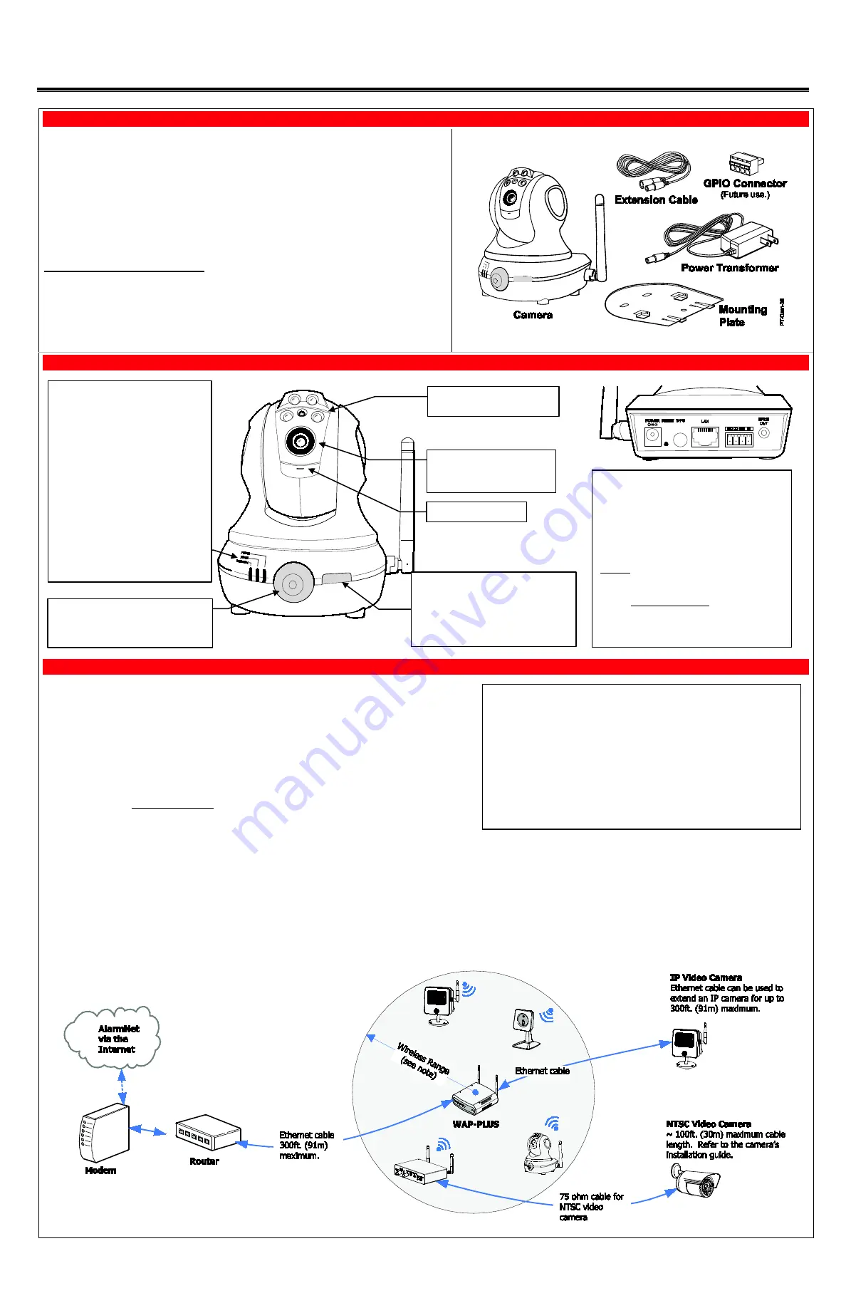
PACKAGE CONTENTS
Component Identification
Planning the camera installation
A camera installation can be as simple as installing one camera, or up to six cameras per
Total Connect account. In large installations it may include a mix of wireless, and wired cameras.
The installer should work closely with the customer to achieve a satisfactory installation.
DO NOT USE THIS BUTTON
NOTE: Ensure the green light is OFF. If
the green light is on:
•
If logged into Total Connect, log out.
•
Click the button once to turn it off.
•
You may log back into Total Connect.
Lens – Fixed lens requires no
focusing. Clean with a soft
tissue and lens cleaner.
Microphone – Not used.
Power
•
Blinking Green – Camera initialization
period, allow up to 2 minutes.
•
Steady Green – Camera is initialized
and power is on.
Active
•
Off – No user is viewing the camera.
•
Blinking Green – User(s) are viewing
this camera.
Network
•
Steady Green – Wireless / LAN is
available.
•
Blinking Green – Network transfers.
•
Blinking Amber – Indicates a WPS
configuration is in process.
•
Steady Amber – WPS fault.
•
Off – Wireless / LAN not connected.
Motion Sensor – PIR motion sensor used
to trigger programmed events, such as
capturing video and sending email
notifications.
Power Connector
– Connect transformer
here.
Reset Button
– Resets IP Camera to default
settings. (Use a paper clip to depress and hold
for 12 seconds, then RELEASE.)
Upon a successful reset, the Power, Active, and
Network LEDs blink 3 times.
WPS Button
– Used during setup to configure
wireless encrypted connectivity.
LAN Connector
– Used for wired connectivity.
When used the wireless is disabled. The
camera must be powered off whenever
connecting or disconnecting the Ethernet cable.
GPIO Connector Socket
– Future use.
Speaker Out
– Not used.
LED Lights – May be manually
activated.
Wireless Range:
The wireless range and bandwidth (data rate) are dependent on the wireless
technology used; as determined by the 802.11b/g/n specifications. This deter-
mines the range and data transfer rate. For instance under ideal conditions,
802.11 g provides up to 125 ft. (38m) range, and 54Mbits/s data rate, and
802.11 n provides up to 230 ft. (70m) range, and 150Mbits/s data rate.
Other factors that reduce the range are thick walls, wire lath, large metal objects,
and the number of cameras sending data.
Because of the many variables, the best way to determine if the installation is
successful, is to test the finished installation by logging into the Total Connect
website and checking each camera.
Layout Considerations:
•
Depending on layout and distances, one or more WAP-PLUS units may be needed.
•
Wireless distance may be reduced by thick walls, wire lath, and large metal objects. For
installations where wireless connectivity is poor, see if the WAP-PLUS has the newer WAP-
ANT5dB antennas. They are approximately 6 inches (15cm) long. If not, they can be
ordered to retrofit the WAP-PLUS.
•
When setting up a wireless configuration in very large buildings or buildings with dense
walls, wireless communications may be marginal. It is best to first configure the system’s
wireless security in the same room (within 20 feet, 6m). Then upon successful configura-
tion, place each camera in the desired location, and verify in Total Connect that everything
works.
•
For installations where multiple WAP-PLUS units are used, label the units to indicate which
IP cameras are linked to which WAP-PLUS.
•
Each IP camera or ACU (Analog Converter Unit) will communicate through its associated
WAP-PLUS.
•
Each WAP-PLUS must be spaced at least 4 feet (1.2m) from other wireless devices.
•
Ensure each device uses the correct power transformer. When needed, secure wires with
cable ties.
•
Refer to the installation guides for the WAP-PLUS, ACU (Analog Converter Unit), and each
IP camera for detailed information about that product.


