background image

INSTALLATION INSTRUCTIONS

Put Bar Code Here

95−7767

Honeywell IdentIPoint™ Intelligent 
Smartcard System

GENERAL

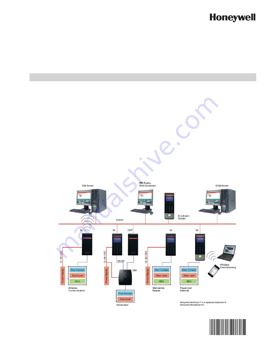
IdentIPoint™ is an intelligent smart card based access control 
system that integrates with Enterprise Buildings Integrator™ 
(EBI) to provide a secure, scalable and a cost effective 
solution for securing defense installations, airports, and 
buildings. This document describes how to install and 
configure the IdentIPoint system.

Fig. 1. IdentIPoint system architecture

Summary of Contents for IdentIPoint

Page 1: ...lligent smart card based access control system that integrates with Enterprise Buildings Integrator EBI to provide a secure scalable and a cost effective solution for securing defense installations airports and buildings This document describes how to install and configure the IdentIPoint system Fig 1 IdentIPoint system architecture ...

Page 2: ...uter Tamper Switch Optical detecting unit dis mounted from wall The readers work with 12V to 24VDC power supply or Power over Ethernet PoE conforming to the IEEE 802 3af standard All software and firmware is remotely upgradeable over the network via EBI All the IdentIPoint readers are designed to work with an optional remote IOM The IOM is used when the control inputs and outputs of the door are d...

Page 3: ...utput Module Unit 1 Mounting Hardware Screws and Wall Anchors 3 each Extra Tamper Resistant Screws 2 Tool for Tamper Resistant Screw 1 Connectors for termination 12 x 2 connections 3 x 3 connections Resistors 2K Color Code RED BLACK RED GOLD 0 5W axial type 5 tolerance 4 Resistors 1K Color Code BROWN BLACK RED GOLD 0 5W axial type 5 tolerance 6 Quick Installation Guide 1 ASSEMBLY MOUNTING AND INST...

Page 4: ...nce all the connections and settings are done hold the reader against the back plate aligning the mounting slots at the back of the reader with their corresponding catches on the back plate and push it downwards until it hooks into place firmly See Fig 8 and Fig 9 6 Use the Allen wrench to tighten the tamper resistant screw at the bottom of the reader into the hole provided on the back plate so as...

Page 5: ...PLATE 4 READER STATUS LED KEYPAD READER FRONT MOUNTING SCREW HOLES 10 OPENING FOR ROUTING CABLES 1 1 2 3 4 5 6 7 8 9 0 LCD HOLE FOR SECURING READER TO BACK PLATE 1 BACK PLATE CATCHES FOR HOLDING READER ON BACK PLATE 4 READER STATUS LED KEYPAD READER FRONT MOUNTING SCREW HOLES 10 OPENING FOR ROUTING CABLES 1 1 2 3 4 5 6 7 8 9 0 LCD HOLE FOR SECURING READER TO BACK PLATE 1 ...

Page 6: ...CH S1 READER BACK 10 100 Activity Power ETHERNET TERMINAL EPOXY POTTED FOR IP65 COMPLIANCE FACTORY RESET SWITCH OPTICAL TAMPER SENSOR WIRING TERMINAL PORTS J9 J10 HOLE FOR TAMPER RESISTANT SCREW CAT5 PIGTAIL HOLE FOR HOLDING RUBBER COVER SHOWN IN CALLOUT RJ45 TERMINAL PLUG M odel B TSTD IdentIPoi ntSta nd ardI nd oo r Power 10 28 VDC PoE M AC ID Ethe rne t 0 04 08 40 AF3 3E M AC ID Wi fi 00408 IOA...

Page 7: ... RED TO FASTEN THE BACK PLATE CLIP ROUND FERRITE CLIP ON THE FIELD ETHERNET CABLE THE FIELD ETHERNET CABLE WITH TWO TURNS WRAPPED ROUTE THE RJ45 CONNECTOR IF REQUIRED AND MOLEX IF REQUIRED AND MOLEX TERMINALS FROM BEHIND THE DRYWALL OR THROUGH THE CONDUITS IN CASE OF CONCRETE WALL AND BRING THEM TOWARDS THE FRONT SIDE OF THE MOUNTING SURFACE THROUGH THE OPENING ON THE READER S OPENING ON THE READE...

Page 8: ... AT THE BACK OF THE READER AS SHOWN HOLD THE 9 AND 10 PIN MOLEX TERMINALS PERPENDICULAR TO THE BACK OF THE READER AND BACK OF THE READER AND ALIGN THEM CORRECTLY WITH PORTS J9 AND J10 PIN 9 PIN 1 PIN 1 PORT J9 PIN 10 PORT J10 10 100 Activity Power Model BTSTD IdentIPoint Standard Indoor Power 10 28 VDC PoE MAC ID Ethernet 0040840AF33E MAC ID Wi fi 00408 IOAF33F Manufactured 2009 07 13 MADE IN CHIN...

Page 9: ...AF3 3E M AC ID Wi fi 00408 IOAF33F M anufactu red 20 09 07 1 3 MADE I N CHINA ON POSITION ON POSITION ON POSITION ON POSITION 1 2 3 4 1 2 3 4 1 2 3 4 1 2 3 4 1 2 3 4 ALIGN THE MOUNTING SLOTS BEHIND THE READER WITH THEIR CORRESPONDING CATCHES ON THE BACK PLATE 10 100 Activity Power M odel B TSTD IdentIPoi ntSta nd ardI nd oo r Power 10 28 VDC PoE M AC ID Ethe rne t 0 04 08 40 AF3 3E M AC ID Wi fi 0...

Page 10: ... WITH THEIR CORRESPONDING CATCHES ON THE BACK PLATE PUSH THE READER DOWNWARDS UNTIL IT HOOKS INTO PLACE FIRMLY READER ASSEMBLY FRONT VIEW 1 2 3 4 5 6 7 8 9 0 READER ASSEMBLY SIDE VIEW ALIGN THE MOUNTING SLOTS BEHIND THE READER WITH THEIR CORRESPONDING CATCHES ON THE BACK PLATE PUSH THE READER DOWNWARDS UNTIL IT HOOKS INTO PLACE FIRMLY READER ASSEMBLY FRONT VIEW 1 2 3 4 5 6 7 8 9 0 ...

Page 11: ...POSITION 1 2 3 4 1 2 3 4 1 2 3 4 1 2 3 4 1 2 3 4 USE THE ALLEN WRENCH TO SECURE THE READER TO THE BACK PLATE WITH THE TAMPER RESISTANT SCREW 1 2 3 4 5 6 7 8 9 0 10 100 Activity Power M odel B TSTD IdentIPoi ntSta nd ardI nd oo r Power 10 28 VDC PoE M AC ID Ethe rne t 0 04 08 40 AF3 3E M AC ID Wi fi 00408 IOAF33F M anufactu red 20 09 07 1 3 MADE I N CHINA ON POSITION ON POSITION ON POSITION ON POSI...

Page 12: ...Standard Indoor Power 10 28 VDC PoE MAC ID Ethernet 0040840AF33E MAC ID Wi fi 00408 IOAF33F Manufactured 2009 07 13 MADE IN CHINA ON POSITION ON POSITION ON POSITION ON POSITION 1 2 3 4 1 2 3 4 1 2 3 4 1 2 3 4 1 2 3 4 Marking Color Descrip on 10 100 Green On when network is 100 MBit Ac vity Orange Flashes on network ac vity Power Blue On if power on Marking Color Descrip on 10 100 Green On when ne...

Page 13: ...see Fig 18 and Table 8 Drop the excess wire lengths behind the drywall Set the S1 DIP switch if the IOM is to be connected to a reader via RS485 See Fig 18 Table 10 and Section RS485 Communication and Termination Setting of Connector and Switch Descriptions topic for more details 6 Set the IOM address as per Fig 18 Table 11 and Sec tion IOM Address Setup of Connector and Switch Descriptions topic ...

Page 14: ...TA AND TAMPER INDICATION LEDS FRONT COVER OF THE IOM HINGE AT THE BOTTOM HOLDING THE TWO PARTS TOGETHER BACK HALF OF THE IOM SIDE KNOCK OUTS FOR CABLE HOLES Power Data Tamper POWER DATA AND TAMPER INDICATION LEDS FRONT COVER OF THE IOM HINGE AT THE BOTTOM HOLDING THE TWO PARTS TOGETHER BACK HALF OF THE IOM SIDE KNOCK OUTS FOR CABLE HOLES ...

Page 15: ...W LIGHT GUIDES CABLE GUIDES 6 COVER TAMPER DETECTION SWITCH PULL OPEN THE FRONT COVER OF THE IOM AND ALLOW IT TO HANG FROM THE HINGE MOUNTING SCREW HOLES 3 PRINTED CIRCUIT BOARD BACK KNOCK OUTS FOR CABLE HOLES 2 WIRING TERMINALS 2 WIRE 13 WIRING TERMINALS 3 WIRE 3 IOM FRONT COVER OPEN HOLE FOR TAMPER RESISTANT SCREW IOM BACK HALF OPEN HOLE FOR TAMPER RESISTANT SCREW LIGHT GUIDES CABLE GUIDES 6 COV...

Page 16: ...ll CUT OPENINGS IN THE DRYWALL FOR ROUTING THE WIRES THE OPENINGS MUST HAVE THE SAME DIMENSIONS AS THAT IN THE BACK HALF OF THE IOM PUNCH THREE HOLES IN THE DRYWALL FOR THE SCREWS USE THE SCREWS PROVIDED TO FIX THE BACK HALF OF THE IOM TO THE DRYWALL NOTE USE ALL THREE HOLES TO FASTEN THE IOM IOM ...

Page 17: ...15 Mounting the IOM on a concrete wall using gang box and conduit GANG BOX EMBEDDED IN WALL PUNCH ADDITIONAL HOLES IN THE WALL FOR THE OTHER SCREWS USE THE SCREWS PROVIDED TO FIX THE BACK HALF OF IOM TO THE GANG BOX AND THE WALL NOTE USE ALL 3 SCREWS TO FASTEN THE IOM ...

Page 18: ... THE CORRECT TERMINALS ON THE PCB USING THE PROVIDED WIRE TERMINAL BLOCKS AFTER WIRING AND OTHER HARDWARE CONFIGURATIONS ARE DONE SHUT THE FRONT COVER OF THE IOM ROUTE THE WIRES THROUGH THE KNOCK OUT HOLES AND FIX THEM TO THE CORRECT TERMINALS ON THE PCB USING THE PROVIDED WIRE TERMINAL BLOCKS AFTER WIRING AND OTHER HARDWARE CONFIGURATIONS ARE DONE SHUT THE FRONT COVER OF THE IOM ...

Page 19: ...er onto the back half of the IOM Power Data Tamper USE THE ALLEN WRENCH TO SECURE THE FRONT COVER OF THE IOM TO THE BACK HALF WITH TAMPER RESISTANT SCREW Power Data Tamper Power Data Tamper USE THE ALLEN WRENCH TO SECURE THE FRONT COVER OF THE IOM TO THE BACK HALF WITH TAMPER RESISTANT SCREW ...

Page 20: ...S4 Cover tamperdetec onswitch Switch Descrip on S1 RS485 Termina onControl DIP switch S2 Ini aliza on Bu on S3 IOMAddress set up DIP switch S4 Cover tamperdetec onswitch S2 Ini aliza on Bu on DIP switch S3 IOM address Posi on Descrip on 1 Address value 1 2 Address value 2 3 Address value 4 4 Address value 8 5 Address value 16 6 Address value 32 7 Address value 64 8 For IOMsetup normallyset toOFF P...

Page 21: ...cate will be issued FOR IOM 1 Power must be provided to the IdentIPoint IOM from a UL294 and or UL1076 listed power supply for access control or one approved by local authority having juris diction 2 Power supply for IOM should be 12 24VDC 3 Power consumption is 1 2W max NOTE For UL294 installations only UL294 and or UL1076 listed power supplies should be used for reader and lock power with requir...

Page 22: ... and reported back to the reader through the RS485 interface Digital Output DO The Digital Output is a current sinking output capable of sinking up to 1A at the rated supply voltage The output can thus be used to drive the door strike magnetic lock lights as well as other Digital Inputs or Supervisory Inputs See Figures 25 through 28 Wire the Readers and IOM 1 Run the field wiring to the readers a...

Page 23: ...STED SEE FIG 25 THROUGH FIG 28 FOR TYPICAL DIODE SUP PRESSION NETWORK WIRING DOOR CONTACTS MUST BE UL LISTED MAXIMUM WIRE LENGTH 500 FT 152 M WIRE TYPE 18 AWG 0 8 SQ MM 50 OHM 60 mA MAXIMUM DOOR CONTACTS ARE ONLY INTENDED FOR MONITORING DOOR POSITION THEY ARE NOT INTENDED FOR CONNECTION TO A BURGLAR ALARM PANEL EXIT SWITCH WIRING MUST BE COMPLETED WITHIN THE PROTECTED AREA OR NOT READILY ACCESSIBL...

Page 24: ...r Ethernet PoE wiring PoE integrates data and power on the same wires without interfering with concurrent network operation PoE delivers 48V of DC power over unshielded twisted pair wiring for terminals consuming less than 13 watts of power PoE can be used with IEEE 802 3af compliant devices in either of the two modes described in Table 3 and shown in Fig 19 and Fig 20 The detailed pin outs are sh...

Page 25: ... negative 4 Vport positive 5 Vport positive 6 Vport negative 7 Vport negative 8 Vport negative STANDARD SOURCE LOAD REMARKS Ethernet RJ 45 connector pin number Source Voltage 1 2 3 4 5 6 7 8 Load Voltage DC Load Connector IEEE 802 3af using data pairs 48 V DC protected RX DC RX DC TX DC spare spare TX DC spare spare embedded Industry standard for embedded PoF IEEE 802 3af using spare pairs 48 V DC...

Page 26: ...to the door lock depending on the type of lock magnetic lock or door strike used and the safety codes to be followed Also connect a power line to the lock See Wiring Other Devices topic for detailed wiring of locks 4 Connect pins 6 7 SAI 0 SAI 0 GND and 8 9 SAI 1 SAI 1 GND to a Request to Exit REX switch and door sensor with proper termination circuit as described in section Supervisory Analog Inp...

Page 27: ...nd Relay C SAI 2 Power GND SAI 2 GND Power IN Frame GND 9 8 7 6 10 DC Power 12 to 24V If PoE is not used To electrical earth IdentIPoint Reader S1 earth If unavailable connect to Power GND DI 0 GND GND DO 0 DI 1 GND Power Min 18 AWG Power Gnd Min 18 AWG Ethernet CAT5 LEGEND GND DO 1 SAI 0 GND GND ILK 0 SAI 1 GND GND ILK 1 SAI 2 485 1KΩ To REX Switch 1KΩ To Door Sensor Signal Power Min 18 AWG Signa...

Page 28: ... Descriptions topic for details on RS485 wiring and termination settings Set the S1 DIP switch on the reader and the IOM accordingly 4 Power to the IOM can be given by connecting the Power OUT Power GND pins 1 2 on J10 of the reader to 12V GND J1 respectively of the IOM Alter natively power to the IOM can also be supplied through a separate 12 24VDC power supply or a common rail 5 Connect pin s NC...

Page 29: ...V If PoE is not used DO 1 DO To LAN To electrical earth If unavailable connect to Power GND To electrical earth If unavailable connect to Power GND Connec ons on Out s n o i t c e n n o C r e d a e r on In reader Ethernet IdentIPoint Reader S1 DC Power 12 to 24V If PoE is not used To electrical earth If unavailable connect to Power GND 1KΩ 2KΩ 2KΩ 1KΩ 1KΩ for 12V 2KΩ for 24V Secure d e r u c e s n...

Page 30: ...ommunication and Termination Setting of Con nector and Switch Descriptions topic for details on RS485 wiring and termination settings Set the S1 DIP switch on the In reader and the IOM accordingly 4 Connect pin s NC NO RL0 C or RL1 C J12 J13 of the IOM to the door lock depending on the type magnetic lock or door strike used and the safety codes to be fol lowed Also connect a power line to the lock...

Page 31: ... 1 DO 0 GND GND DI 0 GND DI 1 DO 0 GND GND DI 0 GND DI 1 DO 0 GND GND DI 0 GND SAI 1 ILK 0 GND GND SAI 0 D1 0 GND GND SAI 1 ILK 0 GND GND SAI 0 D1 0 GND GND SAI 1 ILK 0 GND GND SAI 0 D1 0 GND GND SAI 1 ILK 0 GND GND SAI 0 D1 0 GND GND SAI 1 ILK 0 GND GND SAI 0 D1 0 GND GND SAI 1 ILK 0 GND GND SAI 0 D1 0 GND DO 1 DO 1 DO 1 485 B GND 485 GND SAI 2 ILK 1 GND 485 B GND 485 GND SAI 2 ILK 1 GND 485 B GN...

Page 32: ...e door The RS485 ground signal is not necessary if the IOM is powered by the IdentIPoint reader or if there is a common ground available between the two units WIRING OTHER DEVICES WARNING Use suppressors on door strikes and magnetic locks wherever required Use 14507020 001 diode suppression network Honeywell recommends only DC locks See Fig 25 through Fig 28 for typical diode suppression network w...

Page 33: ...and strike latch 1 Connect 12VDC of the power supply to either the NO or Common pin of Relay 0 or 1 J12 or J13 of the IOM and the 12VDC to the ve pin of the strike latch 2 In the same port J12 or J13 connect the NO or Com mon whichever is left free to the ve pin of the strike latch In this setup the door will remain locked in the absence of power and will be unlocked when power is provided If the ...

Page 34: ...is situation the door will unlock NOTE The above describes one way of wiring the mag netic lock Wiring must be done strictly as per the stipulated safety codes that the building must follow Accordingly the wiring would be either done in a fail safe or fail secure configuration For description of reader pins refer to Table 5 and Table 6 Power Min 18 AWG Power Gnd Min 18 AWG LEGEND Ethernet Power OU...

Page 35: ...r description of IOM pins refer to Table 8 Supervisory Analog Input SAI termination circuit WARNING Exit switch wiring must be completed within the protected area or not readily accessible outside the protected area A typical termination circuit for SAI is shown in Fig 29 1 Connect a 1 K resistor 0 5W axial type 5 toler ance in series with SAI n and the sensor switch 2 Connect a 2 K resistor 0 5W ...

Page 36: ... Signal Connector Wire 1 Power IN RED 2 Power GND BLACK 3 Relay Common ORANGE 4 Relay Normal Close WHITE ORANGE 5 Relay Normal Open WHITE 6 SupervisoryAnalog Input SAI 0 GREEN 7 SAI 0 GND WHITE GREEN 8 SupervisoryAnalog Input SAI 1 BLUE 9 SAI 1 GND WHITE BLUE Connector J10 Pin Number Signal Connector Wire 1 Power Output for Door Strike RED 2 Ground for Door Strike BLACK 3 RS485 A YELLOW 4 RS485 B ...

Page 37: ...nnector J4 1 DIN 0 Digital Input 0 note 2 2 DIN 0 GND Digital Input 0 Ground Connector J5 1 DIN 1 Digital Input 1 note 2 2 DIN 1 GND Digital Input 1 Ground Connector J6 1 SAI 0 Supervisory Analog Input 0 2 SAI 0 GND SAI 0 Ground Connector J7 1 SAI 1 Supervisory Analog Input 1 2 SAI 1 GND SAI 1 Ground Connector J8 1 SAI 2 Supervisory Analog Input 2 2 SAI 2 GND SAI 2 Ground Connector J9 1 SAI 3 Supe...

Page 38: ...lose Connector J13 1 RL 1 Com Relay 1 Dry Contact Common 2 RL 1 NO Relay 1 Dry Contact Normal Open 3 RL 1 NC Relay 1 Dry Contact Normal Close Connector J14 1 RS485 A RS485 bus A non inverting signal signal 2 RS485 B RS485 bus B inverting signal signal 3 RS485 GND RS485 bus Ground Connector J17 1 InterLock 0 Interlock Input 0 Relay 0 bypass activation 2 InterLock 0 GND Interlock 0 Ground Connector ...

Page 39: ...sted pair cables A suitable termination resistor has to be put at the end of the RS485 line to absorb the remaining energy on the line to prevent signal reflection A 100 ohm resistor is chosen as it stays closest to the characteristic impedance of the transmission line IdentIPoint readers and IOMs are both equipped with a termination circuit and do not need an external termination resistor Setting...

Page 40: ...NOTE It is recommended not to attach more than 4 IOM units to the RS485 bus to maintain a reasonable signal response time delay between the reader and the IOMs Hence IOM addresses must be from 1 to 4 only See Fig 32 for S3 DIP switch set tings for up to 4 IOMs Termination OFF Termination ON Termination ON IOM Slave 1 Termination OFF Reader Master Termination ON Pull up ON Pull down ON IOM Slave 2 ...

Page 41: ...rnet mode remains unlit in all other conditions The LEDs on the front of the IOM glow as follows when power is applied to the device Table 12 IOM LED States and Descriptions IOM Address 1 IOM Address 2 IOM Address 4 IOM Address 3 Color RED BLINKING RED GREEN BLINKING GREEN AMBER BLINKING AMBER OFF LED Power _ _ _ On main power _ _ Off Data No Comm Comm exists but invalid data Blinks when there is ...

Page 42: ... both networks Wifi network configuration is not a UL294 listed configuration and should not be used on UL294 applications Logging In 1 Enable wireless by presenting any smart card 2 Create an ad hoc network with IdentIPoint SSID is iPAC10 3 Call up the web interface http 192 168 0 200 NOTE This mode of connecting with the reader will no longer be available after the reader has been dis covered an...

Page 43: ...YSTEM 43 95 7767 I O Out of the box assumes that there is no IO Module 1 If an IO Module is used simply click the link and follow the prompts as shown in figures labeled 1 through 5 2 Position 8 of this switch is the IOM setup dip switch 1 2 3 4 5 ...

Page 44: ...e switch up to put in normal position Door 1 Select the door IO addresses 2 Enter door timings 3 Enter door behavior Hint If common wiring behavior it is quicker to do this from EBI later Testing the Door I O 1 Select the Output Point and the desired level 2 Select the Input Point to see its current value 6 ...

Page 45: ... the scanner The reader scans the finger impression A message Processing Completed appears on the LCD indicating the comple tion of the scanning process While holding or swiping the finger should cover the IR sensor near to FP module other wise the reader functionality will not work 5 A message Provide Your Finger Print Again appears on the LCD of the reader Present your fingerprint on the scanner...

Page 46: ...witch for 10 seconds or more until the reader LED LCD is turned off 3 When the LED LCD is off release the factory reset switch 4 Wait for the reader to restart 5 If using an LCD model the Honeywell banner will appear on the display for a few seconds and then disap pear 6 Within 1 minute the reader LED will start flashing green indicating that the reader has been reset to the factory firmware 7 If ...

Page 47: ...Subpart B sections 107 a 109 a Class B Section 201 to Section 202 section 207 European Union EN 55022 2006EN 60950 1 2001 Canada Canadian ICES 003 Class B WARNING Any changes or modifications not expressly approved by the party responsible for compliance could void the user s authority to operate the equipment This device complies with part 15 of the FCC Rules Operation is subject to the following...

Page 48: ...ty and fitness for a purpose and makes no express warranties except as may be stated in its written agreement with and for its customer In no event is Honeywell liable to anyone for any indirect incidental special or consequential damages The information and specifications in this document are subject to change without notice Copyright 2012 Honeywell International Inc Honeywell Trademarks IdentIPo...

Reviews: