background image

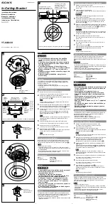
Part List (in this carton)

B.

Side Frame

1 pc.

C.
Side Frame

1 pc.

F.
Stretcher

1 pc.

Home Styles Consumer Assistance:

www.homestyles-furniture.com,

[email protected], 888-680-7460, 877-831-0319

88 5061 761

Storage Stand

For assembly see instructions in carton 88 5061 762

Tools required  for  assembly :

Phillips screwdriver, Drill, 3/8” Drill Bit, Level

IMPORTANT NOTE

.

Carefully remove all the parts from the carton and put
them individually on a soft cloth to prevent scratches
or other damage occurring to the parts.

We have taken great care in the design of this
product and request that you carefully and strictly
follow our assembly instructions to ensure
a completed product as it was designed.

Summary of Contents for 88 5061 761

Page 1: ...ructions in carton 88 5061 762 Tools required for assembly Phillips screwdriver Drill 3 8 Drill Bit Level IMPORTANT NOTE Carefully remove all the parts from the carton and put them individually on a soft cloth to prevent scratches or other damage occurring to the parts We have taken great care in the design of this product and request that you carefully and strictly follow our assembly instruction...

Page 2: ...m 888 680 7460 877 831 0319 Also need the Parts in carton 88 5061 761 M4x32 Wood Screw 12 pcs 1 extra Tools required for assembly Phillips screwdriver Drill 3 8 Drill Bit Level 88 5061 762 Storage Stand IMPORTANT NOTE Carefully remove all the parts from the carton and put them individually on a soft cloth to prevent scratches or other damage occurring to the parts We have taken great care in the d...

Page 3: ...tighten up the Head Cap Bolts in the future After assembly item must be level to work properly Use the included adjustable levelers to level Figure 1 Figure 2 Place Top A upside down on a soft cloth Attach Side Frames B and C to Top A with Head Cap Bolts short tightening the bolts only half way See Figure 1 Attach Stretcher F to unit with Flat Washers Spring Washers and Head Cap Bolts tightening t...

Page 4: ... unit adjust the adjustable levelers on the bottom of unit See Figure 3 Note Unit must be level to work properly Figure 3 STEP 3 Attach Supports E to unit with Wood Screws Turn the unit over to its upright position STEP 4 E E E E Wood Screw ...

Page 5: ...all Screw 1 pc 1 extra tie end loop end Place unit at desired location Drill a hole in wall 3 8 at the appropriate location Insert Anchor into the wall hole and attach Bracket with Wall Screw Attach Bracket at pre drilled hole at top of unit with Machine Screw Use Tipover Restraint to secure Bracket on unit to Bracket on wall See Figure X Put tie end of Tipover Restraint into loop end of Tipover R...

Reviews: