Hitachi NR 90AE (S), Technical Data And Service Manual
The Hitachi NR 90AE (S) is a powerful and reliable nail gun designed for various construction applications. It features exceptional technical specifications and performance, making it a versatile tool for both professionals and DIY enthusiasts. For comprehensive understanding and maintenance, don't forget to download the free Technical Data and Service Manual from manualshive.com.
Share
Download


Reviews:
No comments
Related manuals for NR 90AE (S)
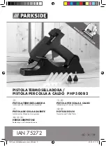
75272
Brand: Parkside Pages: 35

BC-005
Brand: Nitto Kohki Pages: 10

JS-650
Brand: KENTMASTER Pages: 16

R09894
Brand: RIDGID Pages: 44

FSN50
Brand: Haussmann Pages: 19

DGG25
Brand: Toolland Pages: 27

NS289100
Brand: Campbell Hausfeld Pages: 12

TT300
Brand: Omega Pages: 4

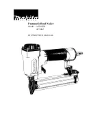
AF631
Brand: Makita Pages: 18

AF600
Brand: Makita Pages: 64

0088381664639
Brand: Makita Pages: 52

AF632
Brand: Makita Pages: 10
AF301ZK
Brand: Makita Pages: 7

AF633
Brand: Makita Pages: 32
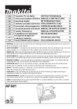
AF601
Brand: Makita Pages: 94

AF503
Brand: Makita Pages: 2

AF501
Brand: Makita Pages: 15

AF505N
Brand: Makita Pages: 80


