Hitachi H 65SD, Technical Data And Service Manual
The Hitachi H 65SD Handling Instructions Manual is an essential resource for users of this powerful tool. This comprehensive manual provides step-by-step instructions and safety guidelines for optimal use. Download the free manual from our website to unlock the full potential of the Hitachi H 65SD and ensure safe operation.
Share
Download


Reviews:
No comments
Related manuals for H 65SD
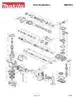
HR4510C
Brand: Makita Pages: 4

HR3210C
Brand: Makita Pages: 4

HR2410
Brand: Makita Pages: 5

HM1500
Brand: Makita Pages: 3

HM1242C
Brand: Makita Pages: 12

HM1242C
Brand: Makita Pages: 3

4340FCT
Brand: Makita Pages: 3

HM1100C
Brand: Makita Pages: 3

HM0810B
Brand: Makita Pages: 16

4341CT
Brand: Makita Pages: 2

4324
Brand: Makita Pages: 2
HK0500
Brand: Makita Pages: 13

TLO 2-18
Brand: Kärcher Pages: 208

SUBLIMAX 1812
Brand: S.E.F.A Pages: 26

KRATOS M1-600B
Brand: GAMDIAS Pages: 14

Pa-50
Brand: LENCO Pages: 2

00223619
Brand: Hama Pages: 40

M12 H
Brand: Milwaukee Pages: 66


