Note:
Unless ordered seperatley the cylinder
is not included in this kit.
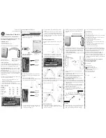
Description
Roller Bolt Deadlock 103x235
Spindle Universal 44mm-63mm & O-ring
Turn/Pull complete
729 Pull Handle & Backplate
Twin-Tech Escutcheon plate assembly
Spring
Indicator disc
Fixings Supplied
Note:
1: If, when fitting the pull handle, the screws make direct contact with the lock-case, please use the shorter (5/8“) screws
included in the fixing pack.
2: Standard Primera Products are designed for internal applications only. For external applications products plated to
“Service Condition 5” should be used.
3: Only use the anti-tamper screws provided.
4: We strongly recommend that impact drivers are not used to install this product.
3S-
56
-729C (TWIN-TECH)
Indicator Lockset
70
PR6130RBD
Roller Bolt
Dead lock
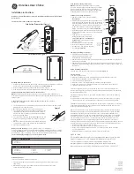
M5 Bolt
from the
other side
of the door
To adjust Roller Catch projection
turn screw anti-clockwise to
increase or clockwise to withdraw.
(Max adjustment 6.5mm-13mm)
Adjusting Roller Catch
Spring rests
against
lockcase
45mm
Emergency
Tool
Access
a
c
b
1
B
A
D1
D2
E
C
X
Y
Z
Z
2
3
4
e
e
B ro
k e n K
ey
!
B ro
k e n K
ey
!
d
PR3S Secondary Barricade Instructions
5.1
This lockset is equipped with an important secondary barricade override mechanism the installation of which is vital to the safety
features of this product. Carefully review diagrams 1-4 below.
5.2
To install this product correctly the spindle must be accessible when the access slider (b) is opened by removing the button head
anti-tamper screw (See diagrams 1 & 2)
5.3
Using the centre of the spindle as a datum (and preferable using a Forstner bit) cut a 45mm dia. hole to create access for the T-Bar
Emergency Tool.
5.4
It is essential to ensure that the T-Bar Spindle Key will fit properly to operate the lock in an emergency. This should be verified at the
point of installation using the tools illustrated below.
UNDER NO CIRCUMSTANCES SHOULD THIS PRODUCT BE FITTED WITHOUT ACCESS TO THESE TOOLS.
5.5
Please refer back to page 2 section 6 to complete this installation.
Note:
The cylinder cut out is made on the external side of the door only and must not go right through the door.
Installing the Twin-Tech pattress and setting the emergency slide cover handing.
1
(Fig 1)
(Fig 4)
(Fig 3)
(Fig 2)
1.
Carefully remove the handing label and the bag containing the hex grub screw and set aside. Take care not to lose the hex grub screw as this is critical
to a successful installation.
2.
Remove the M4 x 6mm button head screw marked Z and slide the emergency cover out of the of the pattress as shown at A.
3.
Secure the pattress to the door as illustrated at B.
4.
With the pattress installed, slide the emergency cover back into the pattress taking note of the two tapped holes marked X and Y as detailed at
drawing C.
5.
Identify the handing of the door according to the detail shown at D1/D2.
6.
For figure 1/4 applications align the centre hole in the emergency slide cover with hole Y.
For figure 2/3 applications align the centre hole in the emergency slide cover with hole X.
7.
Using a 2mm allen key,
insert the hex grub screw through the centre hole in the slide plate and in to either hole (X or Y) and fully tighten. The top of
the grub screw will sit below the surface when tightened. The grub screw limits the movement of the slide plate and prevents it from coming out in use.
8.
To complete the installation of the Twin-Tech pattress, secure the slide plate back in position using the M4 x 6mm button head screw marked Z as
shown at E. The slide plate must move freely and without the spindle interfering with the movement.
IMPORTANT NOTE:
The end of
the spindle should be no more
than 1mm behind the surface of
the Twin-Tech Pattress
09|2015
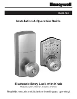
A: This Turn/Pull is equipped with a screw to adjust the projection of the
spindle if required (most likely if the spindle is cut too short in error) see
drawing A
B: When cutting the spindle to the required length, please make sure that
the material is cut from the end marked B as illustrated. The 3 slots at
the opposite end of the spindle C are an important safety feature and
designed to sheer at 50NM to protect the lock and ensure clinical staff
maintain control of the lock at all times. The O-ring in the first slot will
also assist in the retention of the spindle in the nozzle of the Turn/Pull
during normal use.
There must be at least I sheer
point between the end of the
Turn/Pull nozzle & the lockcase.
Important Spindle & Turn/Pull Information
Sheer Points
Do Not Cut Here
O-Ring
Lockcase
Lockcase
Door
A
B
C
Adjust the spindle projection screw
by inserting screwdriver through
the door/lockcase.
The spindle must
engage in the socket
by at least 7mm
Adjust length of spindle by cutting with a
hacksaw at this end. It is important that
the end of the spindle is cut square.
Important Note: Primera products are protected by Intellectual Property Rights including UK and Community Unregistered Design Rights,
UK and Community Registered Designs and UK patents and patent applications.
For further details please contact 01253 508643, [email protected] or visit www.primeralife.co.uk