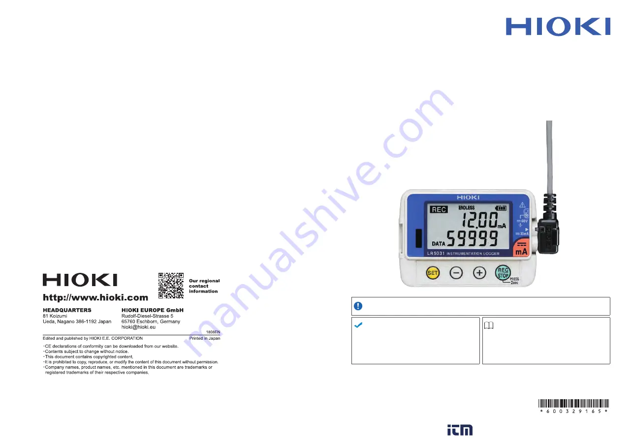
background image

LR5031

Instruction Manual

INSTRUMENTATION LOGGER

EN

Dec. 2018  Revised edition 5

LR5031B980-05


18-12H

Be sure to read this manual 

before using the instrument

Safety Information


p.6

When using the instrument 

for the first time

Troubleshooting

Part Names/Functions 

and Display Indicators


p.14

Maintenance and Service


p.91

Troubleshooting


p.92

Settings List


p.29

Error Display


p.94

www.

.com

[email protected]

1.800.561.8187

Summary of Contents for LR5031

Page 1: ...o read this manual before using the instrument Safety Information p 6 When using the instrument for the first time Troubleshooting Part Names Functions and Display Indicators p 14 Maintenance and Serv...

Page 2: ...2 2 Connecting the Connection Cable 22 2 3 Installing the PC Application Program 23 Chapter 3 Settings___________________________________ 29 3 1 Settings List 29 3 2 Making Settings on the Logger 31 3...

Page 3: ...ations 73 5 8 Converting Over Threshold Data Values 74 Chapter 6 Organizing Data ____________________________75 6 1 Copying and Moving Data 76 6 2 Deleting Data 77 6 3 Combining Data 78 6 4 Extracting...

Page 4: ...shooting 92 9 4 Error Display 94 Appendix_________________________________ A 1 Appendix 1 About Recording Modes A 1 Appendix 2 Recording Intervals and Recording Times A 2 Appendix 3 Battery Life Appro...

Page 5: ...s The screen of this instrument displays characters in the following man ner Introduction Trademarks Notation Indicates a prohibited action p Indicates the location of reference information Indicates...

Page 6: ...y rdg reading or displayed value The value currently being measured and indicated on the measuring instrument dgt resolution The smallest displayable unit on a digital measur ing instrument i e the in...

Page 7: ...utton of the mouse Double click Quickly click the left button of the mouse twice Drag While holding down the left button of the mouse move the mouse and then release the left button to deposit the cho...

Page 8: ...dent or if it fails to operate according to the specifica tions contact your dealer or Hioki representative Quantities in parentheses Verifying Package Contents LR5031 1 LR6 alkaline battery 1 Pre ins...

Page 9: ...incurred during shipping Options LR9801 Connection Cable Cable length Approx 1 m LR5091 Communication Adapter 1 Includes LR5000 Utility Program CD PC appli cation software and USB Cable The latest ver...

Page 10: ...bed in this manual may negate the provided safety features Be certain that you understand the instructions and precautions in the manual before use We disclaim any responsibility for acci dents or inj...

Page 11: ...esult in serious injury or death to the user Indicates that incorrect operation presents a significant hazard that could result in serious injury or death to the user Indicates that incorrect operatio...

Page 12: ...cannot penetrate the enclosure 4 The equipment inside the enclosure is protected against the harmful ef fects of spraying water Operating Precautions Installation Precautions Avoid the following loca...

Page 13: ...n or hard tipped pen because there is a danger of scratching the surface and corrupting the data Do not use adhesive labels Do not expose the disc directly to the sun s rays or keep it in condi tions...

Page 14: ...h and store the data on a computer Quantities in parentheses Measurement Preparation to Data Analysis Required Items LR5031 1 LR6 alkaline battery 1 LR9801 Connection Cable 1 LR5091 Communication Adap...

Page 15: ...8 5 Set the logger to the correct date and time in this case 15 May 2010 13 00 See Real Time Clock Setting p 32 With the LR5000 Utility Program the log ger can be set to the computer time p 41 6 Set t...

Page 16: ...seconds to start recording Confirm that the recording data count is incrementing and that recording is actually occurring See 4 3 p 46 12 Switch the logger display by pressing the and buttons to check...

Page 17: ...y and saving Data can be imported while recording Records up to 60 000 measurements Data is preserved independently of battery state Recording continues for approx 30 s during battery replacement Spla...

Page 18: ...Changes Measurement display contents Changes setting values on the Settings display REC STOP button Hold for two seconds to start stop recording From a setting display switches to measurement display...

Page 19: ...measurement on each channel not displayed when scaling is enabled Measurement Channel MAX indicator Indicates that the value displayed at the right is the maximum MIN indicator Indicates that the valu...

Page 20: ...ing the maximum and minimum values are obtained from all the data measured at each recording interval For statistical recording the maximum and minimum values are obtained from all the data measured e...

Page 21: ...tisti cal recording in stantaneous maximum mini mum and aver age values are recorded at each interval Battery life is shorter Default is off instantaneous value recording Select what hap pens when mem...

Page 22: ...itches to Measurement display When the battery indicator appears settings cannot be changed although they can still be displayed Settings cannot be changed while recording However settings can still b...

Page 23: ...en when the bat tery is depleted and during battery replacement Once the battery indicator appears operation can still continue for about 30 seconds when the battery is removed during recording Testin...

Page 24: ...e following appears Replace the battery to restore normal operation Battery Status Indicator Battery charge remains Fewer blocks within the indicator signify weaker battery charge Replace the discharg...

Page 25: ...tery cover back 2 Hold the battery cover while separating it from the logger 3 Install the battery as shown 4 Align the holes in the battery cover with the projections on the back of the logger 5 Whil...

Page 26: ...ct it to a location with more than 2 5 V as the fuse will melt and measurements cannot be taken Connection Method Align the triangles on the plug body and in front of the connection cable jacks and in...

Page 27: ...LR5000 Utility Program Operating Requirements CPU 1 GHz or faster processor clock RAM At least 512 MB OS Windows XP SP2 or later Windows Vista SP1 or later Windows 7 Library NET Framework 2 0 3 5 Inte...

Page 28: ...rea p 35 Click the icon and click Show Main Screen If the installation screen does not appear Execute X English Setup exe where X is the CD ROM drive letter After starting setup exe follow the on scre...

Page 29: ...ng the program Uninstall Procedure 1 Click Start Control Panel The Control Panel dialog box appears 2 Click Programs and Features The Programs and Features screen appears 3 Select the LR5000 Utility P...

Page 30: ...Setting Screens Logger settings Displays the data import screens Logger data import Display Data Viewing screens Display Data Sorting screens Displays Option screens Displays Help Setting Screens p 3...

Page 31: ...Viewing Screens p 62 View imported data on these screens Select a file to view as a graph or table Example Screens for viewing the latest data Data Import Screens p 59 Import data from the logger wit...

Page 32: ...tings on these screens You can specify the data importing method Example Import Method Setting screen Data Sorting Screens p 75 Sort imported data on these screens You can copy delete move combine and...

Page 33: ...e LR5000 Utility Program can set the logger s clock to match the computer s Yes p 32 Yes p 41 Stop Method Select the processing method when memory becomes full Yes p 33 Yes Included in the recording s...

Page 34: ...8 Scaling Use to scale measured val ues to display as adjusted values No Yes p 39 Alarm Thresholds Set upper and lower thresh old values to display the alarm indicator AL on the logger No Yes p 40 Set...

Page 35: ...t display Settings cannot be changed while recording However settings can still be displayed by pressing the SET button from the Measurement display Recording Interval Setting 1 Press the SET button t...

Page 36: ...ing 4 Repeat this procedure to set the month day hour and minute 5 Press the SET button to accept the set ting The stop method setting is displayed Year Setting display Setting Range 01 01 2010 00 00...

Page 37: ...escription OFF Recording stops when memory becomes full One Time Recording ON Default The oldest data is overwritten when memory is full Endless Recording When memory becomes full during one time reco...

Page 38: ...erval instantaneous recording ON When on measurements are taken once per second and instantaneous maxi mum minimum and average values are recorded at each recording interval sta tistical recording Up...

Page 39: ...am Connecting the Logger LR5091 and Computer 1 Plug the USB cable into the USB port on the LR5091 or LR5092 20 and into a USB port on the computer 2 Dock the logger in the LR5091 or LR5092 20 When doc...

Page 40: ...button The logger s set tings are now reflected in the program 2 Click to select The currently selected logger s back ground is a different color 3 Setting Options Note The displayed settings are thos...

Page 41: ...ox The settings are copied The Auto Power Save feature consumes a small amount of current How can I learn more about changing settings 1 Setting the Basic Settings 2 Settings on the Recording Method t...

Page 42: ...er display blinks until the scheduled start time Setting Options Description Button Operation endless Stops recording by pressing the button on the logger The oldest data is overwritten when memory is...

Page 43: ...scaled result is displayed on the logger Click a tab 3 Settings on the Measurement Method tab Click the Edit button to display the setting dialog box 3 See What is Scaling p 41 Enable scaling Select...

Page 44: ...ured value is out of range OF UF dis played and when a sensor anomaly occurs displayed Setting Options Description Specify by example Enter two known conversion points up to ten digits each Specify by...

Page 45: ...Time Set the logger s clock to match the comput er s clock after confirming the computer s clock is correct Copy and Paste Settings Settings can be copied from anoth er logger p 37 Save Settings Saves...

Page 46: ...t request repair See Requesting repairs p 91 Does the display appear when the battery is installed Display visible No display Request repair See Requesting repairs p 91 Is the logger clock cor rect Co...

Page 47: ...ownward pressure with the stand extended The stand could be damaged Avoid shocking the Z5004 such as by dropping Shock can cause it to be chipped or cracked Do not use the Z5004 where it may be subjec...

Page 48: ...Insert the logger into the LR9901 1 2 The logger can also be attached to a wall or other surface by hanging the strap or attach ment hole on a screw Supported screw head dimensions up to approx 6 8 mm...

Page 49: ...rent to avoid logger damage short circuiting and electric shock resulting from heat building The maximum rated voltage between input terminals and ground is 60 VDC Attempting to measure voltages exce...

Page 50: ...when starting recording after two recording sessions After one second the measurement display reappears Stop Hold the REC STOP button for two sec onds while recording while REC is dis played REC blin...

Page 51: ...10 minutes interval 15 min 00 min 00 s to 45 min 00 s 15 minutes interval 20 min 00 min 00 s to 40 min 00 s 20 minutes interval 30 min 00 min 00 s to 30 min 00 s 30 minutes interval 60 min 00 h 00 min...

Page 52: ...switch from a Setting display to Measurement display To switch to the Measurement display from any other display press REC STOP When power saving p 34 is enabled the display blanks after no operation...

Page 53: ...isplay Note By default Automatically display graph when data is imported on the Options screen is enabled p 82 The data recorded in the logger is imported to the computer automati cally Imported data...

Page 54: ...64 Reloads and re freshes recorded data from a file Displays the Statistical In formation and Item Set tings dialog box when a graph is displayed p 56 Click the buttons to switch between graph and tab...

Page 55: ...Scaling Applies scaling to data on one channel p 67 Power Calculation Performs approximate electric power calculation p 68 Energy Cost Performs approximate energy cost calculation p 69 Operating Rate...

Page 56: ...s select the one dis played closest to the graph Scroll Bar scrolls the graph How can the displayed area be magnified Dotted Box Click 2 1 Drag over the area to be enlarged to enclose it in a dotted b...

Page 57: ...he graph to the clipboard The graph can then be pasted into Microsoft Word etc 1 2 3 4 Time axis tab 1 Automatically sets the time axis to the optimum scale 2 Zooms the display to show only the time s...

Page 58: ...A comment can be entered for each axis 5 Select the item assigned to each axis 6 Sets the Y axis scale for each axis 7 Automatically sets the currently selected Y axis to the optimum scale 8 Specifies...

Page 59: ...easurement value Measured values at A B cursors Statistical data Units The following items appear on the Item Settings tab Display on off Graph line colors and thickness Bar graph display on off Stati...

Page 60: ...ck a maximum or minimum numeri cal value to jump to the relevant cell or to the first if there are multiple relevant cells Time of Recording Recorded Values Blue indicates minimum values and red indic...

Page 61: ...display 2 Click the OK button Check 1 Click 2 Menu Items Contents Select Items Add and clear selection of multiple items display in blue selected with the mouse When there are 600 item in the above l...

Page 62: ...ton If Always specify folder and file before importing on the Options screen is enabled p 82 If you click the Start Importing button data importing starts Screen after importing data p 61 If you click...

Page 63: ...tion click the Start Importing or Next button Method 1 Edit the save destination basic setting Note The Options screen settings p 82 are refreshed Select the save method Three methods are available 4...

Page 64: ...ting data Select Display graph automatically after importing data When not selected the file list is saved and displayed when importing is finished Save Method Screen p 60 Data Import screen p 59 Scre...

Page 65: ...tray notification area and click View Data The Data View screen appears The View latest data tab shows a list of the loggers with data saved on the computer 2 Select the logger from the list Informat...

Page 66: ...on Note You can enter up to 20 characters for Filter by Model Comment Display Table Opens the viewer to display the table of imported or selected data How can past data be viewed On the Search Folders...

Page 67: ...h the desired graph displayed click the Print button See Graph Display Methods 4 5 p 49 4 6 p 59 and 4 7 p 62 4 8 Printing Recorded Data Click Example Graph Printout How can I print only part of a gra...

Page 68: ...the latest data 1 Continued Note If the LR5000 Utility Program is running click View Data on the main screen Click Click 1 If the LR5000 Utility Program is not running on the computer click the icon i...

Page 69: ...ate energy cost calculation p 69 Operating Rate Performs approximate operating rate calculation p 70 Integration Integrates displayed data p 71 Dew Point Performs dew point temperature calculation p 7...

Page 70: ...span Clicking this tab changes the setting options Make set tings on either tab The settings are ap plied to the other tab A B slope offset values 1 2 3 1 1 Setting Options Description Specify by exa...

Page 71: ...Execute button Calculation results are saved Note Click the Finish button to close the Power Calculation dialog box 5 2 Calculating Electric Power Electric power calculations are only approximate so r...

Page 72: ...ish button to close the Energy Cost dialog box 5 3 Calculating Energy Cost Energy cost calculations are only approximate so results do not always equal the true energy cost There is no way to confirm...

Page 73: ...se the Operating Rate dialog box 5 4 Calculating Operating Rate Item and range settings Select the item for operating rate calculation and the time span The time span can also be specified by setting...

Page 74: ...are saved as a new item in the recording file 1 Select the item and time span 2 Click the Execute button Integration results are saved Note Click the Finish button to close the Integration dialog box...

Page 75: ...o confirm that a specified data item is really a tem perature or humidity value Dew point calculation occurs regardless of data type Only the specified temperature and humidity data measured during th...

Page 76: ...Select the calculation operator 3 Click the Execute button Calculation results are saved Note Click the Finish button to close the Two Data Item Arithmetic dialog box 5 7 Two Data Item Arithmetic Calc...

Page 77: ...ding file 1 Select the items and time span 2 Set the upper and lower threshold values and their corresponding conversion val ues 3 Click the Execute button Conversion results are saved Note Click the...

Page 78: ...ars all selections removes check marks Click Click 1 If the LR5000 Utility Program is not run ning on the computer click the icon in the task tray notification area and click Show Main Screen The main...

Page 79: ...nd Moving Data Select the drive 2 Select the folder 3 Select the file Up to 100 can be selected 4 Select the drive 5 Select Copying Data or Moving Data 1 7 Click Select the folder 6 Example Copy a fil...

Page 80: ...Deleting Data Select the drive 2 Select the folder 3 Select the file Up to 100 can be selected 4 Select Deleting Data 1 5 Click Example Delete a file from the folder C Users hioki Documents LR5000 How...

Page 81: ...the folder 3 Select the file Up to 10 can be selected 4 Select Combining Data 1 6 Click Click to specify the desti nation and file name for the combined data file 5 Example Combine file 20110117 with...

Page 82: ...Data Select the drive 2 Select the folder 3 Select Extracting Data 1 7 Click Click to specify the destination and file name for the extracted data file 6 Example Extract the data of January 25th from...

Page 83: ...t run ning on the computer click the icon in the task tray notification area and click Option The Options screen appears 2 Change the settings as needed See 7 1 Changing the Saving Method for Imported...

Page 84: ...r 2 If you select the check box select the folder name 3 How can the save destination folder be changed How can the file naming method be changed File names can be specified as a com bination of up to...

Page 85: ...thod and Logger Settings Displays Task tray notification area icon p 59 Click the Details tab When cleared the Communica tion Utility program has to be started manually How can the device connection m...

Page 86: ...nt accuracy 0 5 rdg 5dgt Accuracy guarantee for temperature and humidity Temperature 23 5 C 73 9 F Humidity 80 RH or less non condensating Temperature coefficient Measurement accuracy 0 05 C add to me...

Page 87: ...nstantaneous recording 60 000 values Statistical recording 15 000 instantaneous maximum minimum and average values Recording start method Logger button operation Instant or scheduled time set by compu...

Page 88: ...ith 1 second recording interval 20 C Dimensions Approx 79W 57H 28D mm 3 11 W 2 24 H 1 10 D Mass Approx 105 g w battery 3 7 oz Dust and water protection rating IP54 EN60529 with connection cable connec...

Page 89: ...temperature and humidity Temperature 0 to 40 C 32 to 104 F Humidity 80 RH or less non condensating Storage temperature and humidity Temperature 10 to 50 C 14 to 122 F Humidity 80 RH or less non conden...

Page 90: ...ng the model 3910 or 3911 Communication Base All Data Logger models 363x to 364x Communication Base models 3910 3911 and 3912 Communication connections Communication with LR5000 series loggers Compute...

Page 91: ...r format Displays up to 600 channels Displays statistical data maximum minimum and average Export functions Export all recorded data displayed in a table in CSV format Paste to Excel all recorded data...

Page 92: ...ment wipe it gently with a soft cloth moistened with water or mild detergent Never use solvents such as benzene alcohol acetone ether ketones thinners or gasoline as they can deform and discolor the c...

Page 93: ...allation Procedure p 23 No measured value is dis played Displays polarity conflict ing with actual current value e g negative dis play when actual current is 10 mA The connection cable plug is not ins...

Page 94: ...icators p 14 The REC indicator disap pears even though record ing has not been stopped The one time recording stop method is selected With one time recording recording stops automatically when memory...

Page 95: ...red in microcomputer ROM RAM Data recording error A fault occurred in recording data or accessing settings Battery voltage is too low for nor mal logger operation Replace the battery See 2 1 Installin...

Page 96: ...ording start time is not recorded in the following case data at 10 00 00 is not recorded Appendix Appendix 1 About Recording Modes Instantaneous Recording Statistical Recording Recording Interval Inst...

Page 97: ...c 16 h 40 min 1 min 41 d 16 h 2 sec 1 d 9 h 20 min 2 min 83 d 8 h 5 sec 3 d 11 h 20 min 5 min 208 d 8 h 10 sec 6 d 22 h 40 min 10 min 416 d 16 h 15 sec 10 d 10 h 15 min 625 d 20 sec 13 d 21 h 20 min 2...

Page 98: ...ndicators 15 Display refresh time 14 Display the graph 65 Display value refresh time 14 Displaying a graph of saved recording data 62 Disposing 91 E Electric power calculations 68 ENDLESS indicator 15...

Page 99: ...23 Screens 26 Uninstall 25 Version upgrading 25 Power save setting 37 Battery life A 2 Power saving 49 Power saving setting 17 34 Preliminary checks 9 Pre Measurement inspection 43 Printing 64 Product...

Page 100: ...orting precautions 5 Troubleshooting 92 U Upper threshold 40 V Version upgrading 25 View Data 65 View data 62 View latest data 62 65 Viewer 50 51 62 63 65 W Wall mounting 45 Wall mounted holder 45 Whe...

Page 101: ...HIOKI E E CORPORATION www com information itm com 1 800 561 8187...

Reviews: