background image

EN

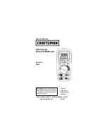
DIGITAL MULTIMETER


Instruction Manual

May 2015  Revised edition 2


DT4251A981-02  15-05H

DT4252

DT4253

DT4254

DT4255

DT4256

www.

GlobalTestSupply

.com

Find Quality Products Online at:

[email protected]

Summary of Contents for DT4252

Page 1: ...IGITAL MULTIMETER Instruction Manual May 2015 Revised edition 2 DT4251A981 02 15 05H DT4252 DT4253 DT4254 DT4255 DT4256 www GlobalTestSupply com Find Quality Products Online at sales GlobalTestSupply...

Page 2: ...es 26 2 3 Using Test Leads 29 2 4 Installation in Measurement Location 32 Using the instrument with the stand 32 Attaching the magnetic strap 32 2 5 Using the Carrying Case 34 3 Performing Measurement...

Page 3: ...c Charge DT4254 DT4255 DT4256 58 4 Using Instrument Conveniently 59 4 1 Selecting the Measurement Range 59 Measuring with the auto range 59 Measuring with the manual range 59 4 2 Retaining the Measure...

Page 4: ...the temperature display unit 77 5 Specifications 79 5 1 General Specifications 79 5 2 Electrical Characteristics 81 5 3 Accuracy Table 83 6 Maintenance and Service 95 6 1 Repair Inspection and Cleanin...

Page 5: ...ing In particular check the accessories panel switches and connectors If damage is evident or if it fails to operate according to the specifications contact your authorized Hioki distributor or resell...

Page 6: ...I 600 V 5 CATIII 300 V CATII 600 V 7 CATIII 600V CATII 600V L4938 7 Test Pin Set L4939 4 Breaker Pin Set L4933 6 Contact Pin Set L4934 5 Small Alligator Clip Set L4935 2 Alligator Clip Set 9243 3 Grab...

Page 7: ...Temperature measurement Only the DT4253 DT4910 Thermocouples K p 50 Temperature measuring junction Exposed type welding Sensor length Approx 800 mm Operating temperature 40 C to 260 C temperature mea...

Page 8: ...he wall surface such as a metal plate for use DT4900 01 Communication Package USB p 72 A communication adapter USB cable PC software and communication specifications are included The instrument data c...

Page 9: ...ain that you understand the instructions and precautions in the manual before use WARNING With regard to the electricity supply there are risks of electric shock heat generation fire and arc discharge...

Page 10: ...ation related to the operation of the instrument or maintenance tasks with which the operators must be fully familiar Indicates a high voltage hazard If a particular safety check is not performed or t...

Page 11: ...Indicates a fuse Indicates a grounding terminal Indicates DC Direct Current Indicates AC Alternating Current Indicates DC Direct Current or AC Alternating Current Symbols for various standards Indicat...

Page 12: ...fine measurement tolerances in terms of rdg reading and dgt digit values with the following meanings rdg Reading or displayed value The value currently being measured and indicated on the measuring in...

Page 13: ...III 1000 V CAT IV 600 V measuring instruments CAT II When directly measuring the electrical outlet receptacles of the primary electrical circuits in equipment connected to an AC electrical outlet by a...

Page 14: ...d during storage or shipping If you find any damage contact your authorized Hioki distributor or reseller Installation Installing the instrument in inappropriate locations may cause a malfunction of i...

Page 15: ...able which could damage the cable insulation To avoid damaging the cables do not bend or pull the leads and the probe bases The ends of the test leads are sharp Be careful to avoid injury For the test...

Page 16: ...id electric shock and or short circuits Hazardous voltage may be generated in a free measurement terminal Do not touch the free terminal Use only test leads and optional equipment specified by our com...

Page 17: ...e open circuit voltage Precautions during shipment Observe the following during shipment Hioki cannot be responsible for damage that occurs during shipment CAUTION During shipment of the instrument ha...

Page 18: ...kage is required Large easily viewable display Backlighting to allow users to read the measurement values in dark environments Dual display Two types of measured values are displayed at the same time...

Page 19: ...ons Front DT4252 DT4255 DT4256 DT4253 DT4254 Some indications are different among the models Display p 22 Operation keys p 17 Rotary switch p 18 Measurement terminals p 20 www GlobalTestSupply com Fin...

Page 20: ...Sets cancels the plus minus judgment function lights up goes off 3 3 Switches cancels the low pass filter and passband settings Sets cancels the display of the relative value REL T Turns off the buzze...

Page 21: ...ent High accuracy 600 0 mV range DC AC voltage measurement Automatic judgment Input impedance 900 k 20 4 Continuity check Resistance measurement Electrostatic capacity Diode test AC measurement Clamp...

Page 22: ...measurement 2 AC current A and frequency measurement 3 1 No 600 0 mV range 2 No 60 00 mA and 600 0 mA range 3 No 600 0 mA range 4 Input impedance 1800 k 20 5 Maximum allowable measurement range 1700...

Page 23: ...he black test lead is connected 3 3 Used for voltage measurement resistance measurement continuity check diode test temperature measurement electrostatic capacity measurement or clamp current measurem...

Page 24: ...can be set on the stand p 32 Test lead holder The test lead can be held Battery cover When replacing the batteries p 26 or fuse p 100 remove the cover See p 26 Strap hole The optional Z5004 Magnetic S...

Page 25: ...c judgment Relative value display measurement other than temperature p 67 5 5 Relative value display during temperature measurement Temperature difference from the standard p 68 6 6 Battery indicator...

Page 26: ...broken Temperature measurement Thermocouple K Corrective action Check that the thermocouple has been connected correctly to the measurement terminal If the display does not change Thermocouple K is b...

Page 27: ...ery Indicator Power shutdown When the charge is 0 less than 4 0 V 0 1 V bAtt appears in the display for 3 seconds and the power is shut down www GlobalTestSupply com Find Quality Products Online at sa...

Page 28: ...ion make sure to select a measurement function and then connect the test leads to the measurement object 2 2 3 3 Red Black 1 1 1 The position of the rotary switch varies depending on the model Turn on...

Page 29: ...ot function properly WARNING To avoid electric shock disconnect the test leads from the object to be measured before replacing the batteries To avoid the possibility of explosion do not short circuit...

Page 30: ...in the instrument To avoid corrosion from battery leakage and or damage to the instrument remove the batteries from the instrument if it is to be kept in storage for an extended period The indicator a...

Page 31: ...cover on the rear of the instrument 5 Remove the battery cover 6 Remove all of the old batteries 7 Insert 4 new batteries LR03 being careful to the battery polarity 8 Reattach the battery cover 9 Sec...

Page 32: ...performing measurements in the CAT III and CAT IV measurement categories See Measurement categories p 9 If the sleeves are inadvertently removed during measurement stop the measurement CAUTION To ensu...

Page 33: ...Attach to the metal pins to prevent short circuit accidents Barrier Represents the safe handling distance from the metal pins During measurement do not touch the area between the barrier and the tip...

Page 34: ...way in Connecting to the instrument 1 1 2 2 1 Turn the rotary switch to the desired measurement function 2 Connect the test leads to the relevant measurement terminals Besides the current measurement...

Page 35: ...nclined surface When the instrument is set on the stand do not apply a strong force above Doing so may damage the stand Attaching the magnetic strap Attach the optional Z5004 Magnetic Strap to the ins...

Page 36: ...r dust or condensation In those conditions the Z5004 may be decomposed or deteriorated The magnet adhesion may be diminished In such case the instrument may not be hung in place and may fall Do not br...

Page 37: ...Carrying Case C0201 Carrying Case The test leads can be stored The instruction manual can be stored at the bottom of the case The instrument can be stored www GlobalTestSupply com Find Quality Produc...

Page 38: ...Case Removing the cover 1 Unfasten the button on the side of the cover marked with OPEN 2 Flip the cover to the back 3 Fasten the button www GlobalTestSupply com Find Quality Products Online at sales...

Page 39: ...Case Using the instrument with a strap around the neck 1 1 1 Unfasten the button 2 2 Secure the button at the position shown in the figure www GlobalTestSupply com Find Quality Products Online at sale...

Page 40: ...The terminals are not contaminated with debris Remove contamination with a cotton swab The coating of the test leads is neither broken nor frayed or the white portion or metal part within the lead is...

Page 41: ...rately short circuit the test leads and then check the display Red Black For the DT4254 Check that there is nothing abnormal in operation check 2 p 39 Normal A buzzer sounds and the value stabilizes a...

Page 42: ...t to measure the commercial power supply and then check the display Red Black The position of the rotary switch varies depending on the model Normal An already known value appears In this example the...

Page 43: ...is not obtained the value higher than that is displayed replace the fuse p 100 DT4253 check method Action 1 Remove the fuse from the instrument p 100 2 Reattach the battery cover 3 In the resistance m...

Page 44: ...se p 100 4 Check that the electric charge detection function operates normally Only the DT4254 DT4255 and DT4256 Check method Action Position the detector on a known power supply such as a power outle...

Page 45: ...erve the following to avoid short circuit accidents Always verify the appropriate setting of the rotary switch before connecting the test leads Move the test leads away from the measurement object bef...

Page 46: ...probes is exceeded the instrument may be damaged resulting in personal injury Do not use the instrument in such locations See Measurement categories p 9 The auto ranging function of this instrument a...

Page 47: ...d Black 1 1 4 8 Using Plus Minus Judgment Function for Measurement Value DT4254 DT4255 DT4256 p 71 is only used for the DT4252 The position of the rotary switch varies depending on the model www Globa...

Page 48: ...dged and the voltage is measured The instrument does not measure both AC and DC at the same time 4 8 Using Plus Minus Judgment Function for Measurement Value DT4254 DT4255 DT4256 p 71 AC voltage DC vo...

Page 49: ...not indicate a malfunction of the instrument The sensitivity of the frequency measurement is regulated by range Minimum sensitivity voltage Minimum sensitivity current p 85 When the value is less tha...

Page 50: ...rn off the power to the measurement circuit Otherwise electric shock may occur or the instrument may be damaged 2 2 3 3 Red Black 1 1 Detection Threshold Buzzer Red LED Short circuit detection 25 10 S...

Page 51: ...ED WARNING Before measuring be sure to turn off the power to the measurement circuit Otherwise electric shock may occur or the instrument may be damaged Cathode Anode 3 3 Red Black 1 2 2 1 1 In the ca...

Page 52: ...ve value display relative function p 67 in advance WARNING Before measuring be sure to turn off the power to the measurement circuit Otherwise electric shock may occur or the instrument may be damaged...

Page 53: ...t to the thermocouple 1 1 2 3 3 2 2 DT4910 Red Black Be careful to observe the polarity when connecting the thermocouple When a breaking state of the Thermocouples K is detected Checking the temperatu...

Page 54: ...uple may be malfunctioning Check this with the following procedure 1 Short circuit the V and COM terminals of the instrument using the test leads The ambient temperature is displayed To step 2 The amb...

Page 55: ...shock may occur or the instrument may be damaged Do not measure the capacitor which has been charged 2 2 3 3 Red Black 1 1 When measuring the polar capacitor Connect the V terminal red test lead to t...

Page 56: ...d then connect the test leads Measuring DC AC Current Function A Selected to measure 600 0 A DC or less DT4253 mA Selected to measure 60 00 mA DC or less DT4253 The conversion of 4 20 mA can be checke...

Page 57: ...ured current value of the burner flame varies with the input impedance of the instrument The A input impedance of this instrument is approx 1 k DT4252 DT4256 Red Black 3 3 1 1 2 2 Load Power supply Th...

Page 58: ...ntation system can be converted to 0 to 100 and checked 4 mA 20 mA 0 100 An input less than 4 mA or exceeding 20 mA is displayed with Red Black Sensor Two wire transmitter Distributor Output signal 4...

Page 59: ...on probe be sure to read the Instruction Manual which accompanies the optional clamp 4 1 1 3 5 5 Set the clamp on probe and the instrument to the same range 9704 Conversion Adapter Clamp on probe 970...

Page 60: ...y one conductor Single phase 2 wire or three phase 3 wire cables clamped together will not produce any reading NO OK NO When the measured value and OVER blink The measured value exceeds the maximum di...

Page 61: ...c charge properly do not use the instrument with test leads wrapped around the instrument The sensitivity of electric charge detection deteriorates Check that the detection function operates normally...

Page 62: ...range cannot be changed Measuring with the auto range RANGE AUTO lights up When the measurement function is switched using the rotary switch the auto range is enabled Measuring with the manual range P...

Page 63: ...ically When HOLD is pressed and held for at least 1 second auto hold mode starts HOLD blinks and when the measured value stabilizes it is retained HOLD lights up Retaining the measured value manually...

Page 64: ...a beeping sound is generated and the value is retained HOLD lights up When the test leads are moved away from the measurement object reconnected again and the measured value stabilizes a beeping sound...

Page 65: ...lly The threshold is not exceeded Auto hold Example 99 0 V Measured value Connect to the measurement object Release Release Release Connect Connect Stable range Dead zone Conceptual diagram AC voltage...

Page 66: ...0 or less Continuity check 100 or less 4900 or more Resistance 100 or less 4900 or more Diode 40 or less 1460 or more AC Clamp 50 100 25 50 100 25 50 or less each range 50 100 25 50 100 25 50 or less...

Page 67: ...side of the inverter This function can be used when measuring the AC voltage AC DC voltage automatic judgment AC current and clamp AC current The passband setting for the low pass filter can be selec...

Page 68: ...alue V Filter OFF Passband 500 Hz Passband 100 Hz AC voltage 600 0 V range 100 V input Frequency at 100 V input Hz Example Power frequency on an aircraft or marine vessel is 400 Hz When voltage is 100...

Page 69: ...is pressed the main display is changed MAX MIN AVG MAX The current measured value can be checked in the sub display Changing back to the normal display Press for at least 1 second The maximum MAX and...

Page 70: ...he following measurement function is selected this function is disabled AUTO V Diode Electric charge detection When the relative function is enabled the range settings cannot be changed Effective meas...

Page 71: ...ed press for at least 1 second The standard temperature is fixed as T1 The currently measured temperature is displayed as T2 alternately with T1 The temperature difference T T2 T1 is displayed in the...

Page 72: ...measurement 1 Select the measurement function 2 Connect the test leads to the measurement terminals 3 Allow the test leads to short circuit 4 Press for at least 1 second After zero adjustment 0 0 5 M...

Page 73: ...t to enabled lights up It is also possible to disable the auto power save function At 30 seconds before the instrument enters the sleep mode the APS blinks to indicate its status To continuously use t...

Page 74: ...voltage is less than the following standard value a buzzer sounds and the red LED lights up This function is useful for checking for any incorrect connection of the DC power Standard value 10 V or le...

Page 75: ...n package Attaching the USB cable to the instrument p 73 Connect to the PC The virtual COM ports of the PC can be used as the USB interface The instrument recognizes the COM1 to COM256 virtual ports C...

Page 76: ...ication appears in the display When is lit the operation keys of the instrument is disabled During communication do not disconnect the USB cable Disconnecting the cable stops the communication In that...

Page 77: ...tion are lost When the operation key is released after changing the setting the regular display then reappears Turn on the power while pressing the operation key Turn the rotary switch from OFF Settin...

Page 78: ...and OFF is switched at each operation Checking the software version First position from OFF Example Ver 1 00 Displaying all indicators Third position from OFF Check that there are no missing indicator...

Page 79: ...the adjustment source Second position from OFF FACT Indicates that the settings have been adjusted by Hioki USER Indicates that the settings have been adjusted by the user www GlobalTestSupply com Fin...

Page 80: ...ly 2 Press and hold and simultaneously 3 Press to change the temperature unit 4 Press and hold to save the setting 5 After turning the power OFF turn the rotary switch to TEMP and check the temperatur...

Page 81: ...ronment Indoors pollution degree 2 altitude up to 2000 m 6562 ft Operating temperature and humidity Temperature 25 C to 65 C 13 0 F to 149 0 F DT4254 DT4255 DT4256 10 C to 50 C 14 0 F to 122 0 F DT425...

Page 82: ...a test lead holder Instruction Manual LR03 alkaline battery 4 not installed in the instrument Options See Options sold separately p 2 Replacement parts DT4253 250 mA 1000 V fuse for current terminal...

Page 83: ...Infinity 0 auto range operation 6 Display update rate Measured value 5 times s excluding electrostatic capacity frequency temperature after the range is fixed 7 0 05 to 5 times s varies depending on t...

Page 84: ...urement input short circuited backlight lit Rated power 36 mVA 20 or less Power voltage 6 0 V DCV measurement backlight off 12 mVA 20 or less Power voltage 6 0 V sleep mode Continuous operating time A...

Page 85: ...Other conditions The accuracy of the two connected L4931 Extension Cable Sets 3 m is guaranteed rdg reading or displayed value The value currently being measured and displayed on the measuring instrum...

Page 86: ...range for frequency are also displayed The accuracy is not specified for strain waveforms outside the range of 40 Hz to 1 kHz For 100 Hz with the filter ON 1 5 rdg is added to the accuracy specificati...

Page 87: ...to 99 99 kHz 3 000 V or more 24 00 V or more 240 0 V or more 400 V or more The voltage input is up to 2 107 V Hz appears when no measurement can be made 1 The measurement range from 5 00 Hz is only fo...

Page 88: ...5 1001 V to 1700 V 2 0 rdg 5 dgt Overload protection 1100 V DC 1870 V DC 2 1100 V AC or 2 107 V Hz energized for 1 minute Auto range movement threshold 6000 counts or more for upper range 540 counts o...

Page 89: ...be added to 5 or less of the range Accuracy guarantee range for frequency 40 Hz to 1 kHz Measured values outside the accuracy guarantee range for frequency are also displayed The accuracy is not spec...

Page 90: ...dgt 200 A 20 6 000 k 0 7 rdg 5 dgt 1 3 dgt 2 100 A 20 60 00 k 0 7 rdg 5 dgt 1 3 dgt 2 10 A 20 600 0 k 0 7 rdg 5 dgt 1 3 dgt 2 1 A 20 6 000 M 0 9 rdg 5 dgt 1 3 dgt 2 100 nA 20 60 00 M 1 5 rdg 5 dgt 1...

Page 91: ...o range movement threshold 1100 counts or more for upper range 100 counts or less for lower range 9 Diode Range Accuracy Measurement current 1 500 V 0 5 rdg 5 dgt 1 8 dgt 2 0 5 mA 20 Open circuit volt...

Page 92: ...re compensation stability time 120 minutes When the instrument environmental temperature changes quickly from 50 C to 23 C 122 0 F to 73 4 F 2 The F display is activated using a special instrument ope...

Page 93: ...0 5 rdg is added to the accuracy specification between 40 Hz and 500 Hz and the accuracy is not specified in 500 Hz or more 12 DC Current A Range Accuracy Input impedance 60 00 A 0 8 rdg 5 dgt 1 k 5 6...

Page 94: ...g 3 dgt 1 8 rdg 3 dgt 35 m 30 Overload protection 11 A 1000 V fuse breaking capacity 50 kA AC 30 kA DC Crest factor The crest factor is 3 up to 4000 counts and reduces linearly to 2 at 6000 counts exc...

Page 95: ...z and the accuracy is not specified in 500 Hz or more 2 DT4256 16 Electric charge detection Range detection sensitivity Detection voltage range 1 Detection target frequency Hi 40 V AC to 600 V AC 50 H...

Page 96: ...the instrument or installation environment We recommend that the calibration frequency is determined in accordance with the status of the instrument or installation environment and that you request th...

Page 97: ...sportation Include cushioning material so the instrument cannot move within the package Be sure to include details of the problem Hioki cannot be responsible for damage that occurs during transportati...

Page 98: ...ntinuity of the test leads p 38 If the test lead is broken replace the lead Check that the test leads have been inserted at the ends Check that the measurement method is correct If no problems have be...

Page 99: ...te with the instrument the optional DT4900 01 Communication Package is required It is possible to control multiple instruments via USB ports The instrument cannot communicate with the PC Is the commun...

Page 100: ...r appears in the display it is necessary to repair the instrument Contact your authorized Hioki distributor or reseller Err 002 ROM error Adjustment data Err 004 EEPROM error Memory data Err 005 ADC e...

Page 101: ...ay damage the instrument and result in personal injury Specified fuses Rating Specifications For A mA terminal DT4253 250 mA 1000 V Manufacturer HOLLYLAND Breaking characteristic Fast blow type Breaki...

Page 102: ...strument The tip of the test lead may bend 1 Remove the test leads from the instrument 2 Set the rotary switch to OFF Screw Rear Sc c c 3 Using a Phillips screwdriver remove the screw 1 location from...

Page 103: ...he true RMS method the high frequency component is also included and displayed In the average method the input waveform is handled as a sine wave where no skew is included only single frequency The av...

Page 104: ...13 09 www GlobalTestSupply com Find Quality Products Online at sales GlobalTestSupply com...

Page 105: ...ct your supplier or the International Sales and Marketing Department at Hioki headquarters In the interests of product development the contents of this manual are subject to revision without prior not...

Reviews: