Multiple instructions:
Consult the specific part
Read and understand
the instructions before
undertaking any work on
the unit
RET
AIN FOR FUTURE REFERENCE
Incorporated in this document are the following:
• Declaration of conformity
• Technical manual
• Dimensional drawing
• Wiring diagrams
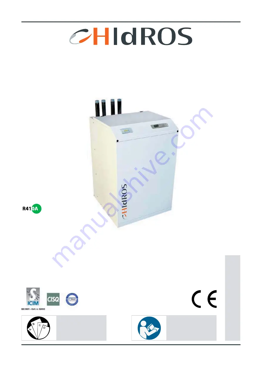
TECHNICAL MANUAL
WATER CHILLERS
WSA
SERIES
MTEC.3800.GB-B-1 Operation and maintenance WSA series English Rev. 07-2013
Original Instructions