background image

USE ONLY HAYWARD GENUINE REPLACEMENT PARTS

HRSN2IOM Rev D   ECR 102V

Page 1 of 36 

Hayward Flow Control
1-888-HAY-INDL (1-888-429-4635)

www.haywardflowcontrol.com

TO PREVENT POTENTIAL INJURY OR DAMAGE TO PROPERTY, READ THIS MANUAL CAREFULLY AND COMPLETELY. 

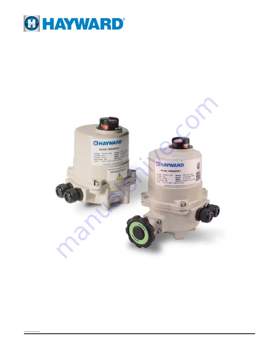
INSTALLATION, OPERATION AND 

MAINTENANCE INSTRUCTIONS

HRSN2 Series

Back to TOC

Summary of Contents for HRSN2 series

Page 1: ...102V Page 1 of 36 Hayward Flow Control 1 888 HAY INDL 1 888 429 4635 www haywardflowcontrol com TO PREVENT POTENTIAL INJURY OR DAMAGE TO PROPERTY READ THIS MANUAL CAREFULLY AND COMPLETELY INSTALLATION OPERATION AND MAINTENANCE INSTRUCTIONS HRSN2 Series Back to TOC ...

Page 2: ...ections WARNING Failure to bond all electrical equipment to system structure will increase risk for electrocution and could result in injury or death To reduce the risk of electric shock see installation instructions and consult a professional electrician on how to bond all electrical equipment Also contact a licensed electrician for information on local electrical codes for bonding requirements C...

Page 3: ...C On Off 32 HRSN2A 2S 12 24VAC VDC Proportional 33 HRSN2A 2S 120 230VAC On Off 34 HRSN2A 2S 120 230VAC Proportional 35 Notice The HRSN2 Series is produced in two distinct versions one with a manual override shaft on the bottom of the actuator HRSN2A 2R and the other with a manual hand wheel on the side of the actuator HRSN2B 2S Notice ALL HRSN2 Series actuators rotate CW to CLOSE the output shaft ...

Page 4: ...4 75 Motor Protection Temp Class 155 C Class F 180 C Class H Motor Starts per hour Max 600 1200 All Manual Override Bottom 8mm Hex Shaft Hand Wheel Bottom 8mm Hex Shaft Hand Wheel Environmental Rating NEMA 4 4X IP67 Electrical Entry 2 1 2 EMT or Polyamide gland Control On Off Proportional 2 Pos RO RC 3 Position Auxiliary Switch End of Travel 2 Form A Volt Free Rated 3A 250vac Ambient Operating Ran...

Page 5: ...tings and proper conduit drainage Supply power to the unit to keep the internal heater warm at the time of installation SHIPPING AND HANDLING INSTALLATION NOTES These actuators are designed to be used between a horizontal and upright position Do NOT mount the assembly with the actuator top below a horizontal position i e upside down When installing conduit use proper techniques for entry into the ...

Page 6: ...accept 14AWG down to 18AWG solid or stranded wire TERMINAL NUMBERING HAS 1 AT THE BOTTOM 6 Refer to your product part number to determine which wiring diagram to follow when wiring up the actuator 7 Note that although terminals are labeled as 1 8 and A D not all terminals are used on all models Removable terminal blocks facilitate ease of field wiring and testing To remove a terminal block from th...

Page 7: ...and CCW rotation of the shaft will OPEN the actuator WARNING DO NOT operate manual override when power is present Geartrain damage and personal injury may occur DO NOT operate manual override beyond 90 of rotation on proportionally controlled models it will permanently damage the position potentiometer Do not use powered tools to turn the manual override it will DAMAGE the gear train or motor and ...

Page 8: ...felt Ideally the set screw rides along the camshaft Now SLOWLY rotate the hex key to the RIGHT pushing the cam until you hear the click on the second switch The click means correct adjustment has been achieved Tighten the cam set screw 5 Apply power and test for the correct CCW position Drive the actuator CW at least 15 20 degrees Drive the actuator CCW until the cam stops the electrical travel Ch...

Page 9: ...h typically used to indicate the actuator reached its CCW position 2 Drive the actuator to its CCW position Use a 2 5mm hex key to free up the cam set screw Once it is free adjust it as described below Rotate the hex key to the LEFT 10 15 degrees until you hear a click This will reset the switch roller arm Gently tighten CW the set screw only until slight pressure is felt Ideally the set screw rid...

Page 10: ...the setting of this procedure is incorrect the sector gear will overdrive and damage the potentiometer HRSN2A 2R Models initial gear mesh setup Because the potentiometer itself has a limited angle of rotation and can be easily damaged by overdriving its limits take care to initially set it up With the sector gear setscrews loosened as described lift the sector gear so it is not meshed with the pin...

Page 11: ...rive CCW OPEN Notice The handwheel on HRSN2B 2S models is disengaged from the drive system during normal operation Also the HRSN2B 2S models have LIMITED rotation angles of less than 105 There are HARD mechanical stops in the geartrain which prevent the manual or automatic operation of the actuator beyond those limitations WARNING Attempts to use the hand wheel system to move the geartrain beyond ...

Page 12: ...ides along the camshaft Now SLOWLY rotate the hex key to the RIGHT pushing the cam until you hear the click on the bottom switch The click means correct adjustment has been achieved Tighten the cam set screw 2 Apply power and test for the correct CW position Drive the actuator CCW at least 15 20 degrees Drive the actuator CW until the cam stops the electrical travel Check to be sure this is the co...

Page 13: ...itch typically used to indicate the actuator reached its CCW position 2 Drive the actuator to its CCW position Use a 2 5mm hex key to free up the cam set screw Once it is free adjust it as described below Rotate the hex key to the RIGHT 10 15 degrees until you hear a click This will reset the switch roller arm Gently tighten CW the set screw only until slight pressure is felt Ideally the set screw...

Page 14: ... the setting of this procedure is incorrect the sector gear will overdrive and damage the potentiometer HRSN2B 2S Models initial gear mesh setup Because the potentiometer itself has a limited angle of rotation and can be easily damaged by overdriving its limits take care to initially set it up With the sector gear setscrews loosened as described lift the sector gear so it is not meshed with the pi...

Page 15: ... or uncontrolled movement to keep the actuator from possibly driving past the limits of the valve or damper attached and to simply keep the actuator in a known position for a quick efficient installation WARNING LETHAL voltages may be present insidethisactuator II If it does NOT move proceed to step 3 2 Check control wiring to terminals 1 8 on the actuator A Remove field wiring from terminals 4 6 ...

Page 16: ... electronic position of the actuator i e 4mA full CW and 20mA full CCW positions reference actuator terminals 5 and 6 5 Generate a CCW move command 20mA and verify the DIRECTION of the position indicator is CCW A The actuator should run CCW and run until it reaches its CW end of travel position B Measure terminals 5 and 6 to read 20mA 10vdc The end stop travel cams of this actuator have been facto...

Page 17: ...hen the respective torque switch levers are depressed IMMEDIATELY STOP the operation of the actuator and refer to the Table of Contents for the section to reference for the corrective action needed 7 Check the full scale response of the analog signals into and out of the actuator by referring to the section Calibration Proportional Control for the proper voltage of the actuator 8 If the actuator s...

Page 18: ... 6 above B This procedure reads and saves the potentiometer readings into microcontroller EEPROM C Loss of power does not erase these settings D During the CCW drive process the grn LED D6 will be ON and turns off when CCW end of travel is reached E During the CW drive process the red LED D7 will be ON and turns off when CW end of travel is reached 5 Upon completion of this procedure the blu LED D...

Page 19: ...tor Flashes once every four seconds to indicate normal CPU activity D18 red POWER Indicator On indicates power is applied to unit S2 Feedback Mode 2 10vdc 4 20mA 0 10vdc not used S1 Signal Mode 1 5vdc 2 10vdc 4 20mA JP6 0 10vdc not used JP6 JP6 JP6 Default factory setting is 4 20mA In Out W2 Trims Full CW FB Out 4mA W1 Trims Full CCW FB Out 20mA to DECREASE 4mA setting to DECREASE 20mA setting S3 ...

Page 20: ... cam positions are reached B There are NO LED indicators to advise when the actuator is running 5 When the actuator stops press the OP pushbutton ONCE A The actuator will drive to its full CW Closed position and stop when the pre set cam positions are reached B There are NO LED indicators to advise when the actuator is running 6 When the actuator stops press the CL pushbutton ONCE 7 After data is ...

Page 21: ...ET OPEN CLOSE SET CPU Running Indicator VR2 Trims Full CCW FB Out 20mA to DECREASE 20mA OUT Red 24VDC Blk Hot 24VAC Com Fault OUT Dry Contact DIP ON OFF FUNCTION 1 4 20mA 0 2 10V Input 2 0 10V 2 10V 4 20mA 3 4 20mA 0 2 10V Feedback 4 0 10V 2 10V 4 20mA 5 Mod On Off Control DIP FUNCTION 4 Off Factory Function 4 On Factory Function 3 Off DA Mode 4mA Closed CW 3 On RA Mode 20mA Closed CW 1 Off 2 Off ...

Page 22: ...s improperly set REMOVE POWER Check to see if cams rotate freely on the cam shaft using your finger Cams MUST be secure and set according to the procedures in the Adjusting CW CCW End of Travel section Motor is extremely hot to the touch Control noise or excessive duty cycle Check for stray voltage fluctuations on the incoming control signals The on off line voltage actuators have a maximum 25 duty ...

Page 23: ...evice exceeds that of the actuator Increase actuator size With the actuator removed from the mechanical equipment manually rotate the valve or damper through its intended range of travel to check for mechanical problems Insufficient power supply and or incorrect wire size during installation Measure the voltage between terminals 1 2 WHILE commanding the actuator to move The measured voltage cannot...

Page 24: ...Aluminum Casting NEMA 4X Protection NEMA 4X Cover Seal Captured Cover Screws UV Impact resistant protective Indicator Cover NEMA 4X Sealed Conduit Entry 2 1 2 ISO5211 Mounting System ISO5211 Double Square Female Drive Socket Override Handwheel version Steel Cut Gearing Inside the actuator Easily accessible switch cam stacks Modular Control Cards including internal heater 2 position 3 position prop...

Page 25: ...flowcontrol com COVER REMOVAL CLEARANCE OVERRIDE WEIGHT MODEL TYPE IN MM MM TURNS FOR 90 LBS KG HRS2A on off All 4 93 125 8mm hex Approximately 7 5 turns 90 6 6 3 0 Mod HV 8 8 4 0 HRS2R on off All 4 93 125 Approximately 7 5 turns 90 6 6 3 0 Mod HV 8 8 4 0 MECHANICAL DATA DIMENSIONAL DATA TYPICAL HRS 2A 2R EXCEPT 12 24V PROPORTIONAL Back to TOC ...

Page 26: ...ww haywardflowcontrol com COVER REMOVAL CLEARANCE HANDWHEEL WEIGHT MODEL TYPE IN MM IN MM TURNS FOR 90 LBS KG HRS2B on off All 4 93 125 2 46 62 5 12 turns 90 7 0 3 2 Mod HV 9 3 4 2 HRS2S on off All 4 93 125 2 46 62 5 12 turns 90 7 0 3 2 Mod HV 9 3 4 2 MECHANICAL DATA DIMENSIONAL DATA TYPICAL HRS 2B 2S EXCEPT 12 24V PROPORTIONAL Back ...

Page 27: ...USE ONLY HAYWARD GENUINE REPLACEMENT PARTS HRSN2IOM Rev D ECR 102V Page 27 of 36 Hayward Flow Control 1 888 HAY INDL 1 888 429 4635 www haywardflowcontrol com NOTES Back to TOC ...

Page 28: ...A 4X Protection NEMA 4X Cover Seal Captured Cover Screws UV Impact resistant protective Indicator Cover NEMA 4X Sealed Conduit Entry 2 1 2 ISO5211 Mounting System ISO5211 Double Square Female Drive Socket Override Handwheel version Inside the actuator Easily accessible switch cam stacks Removable Wiring Block Modular Control Cards including internal heater proportional control custom interfaces Ba...

Page 29: ... 888 429 4635 www haywardflowcontrol com COVER REMOVAL CLEARANCE OVERRIDE WEIGHT MODEL TYPE IN MM MM TURNS FOR 90 LBS KG HRS2A Mod LV 4 93 125 8mm hex Approximately 7 5 turns 90 14 3 6 5 HRS2R Mod LV 4 93 125 Approximately 7 5 turns 90 14 3 6 5 HRS 2A 2R 12 24V PROPORTIONAL MECHANICAL DATA DIMENSIONAL DATA Back to TOC ...

Page 30: ...AY INDL 1 888 429 4635 www haywardflowcontrol com COVER REMOVAL CLEARANCE OVERRIDE WEIGHT MODEL TYPE IN MM MM TURNS FOR 90 LBS KG HRS2B Mod LV 4 93 125 2 46 62 5 12 turns 90 14 7 6 7 HRS2S Mod LV 4 93 125 2 46 62 5 12 turns 90 14 7 6 7 DIMENSIONAL DATA HRS 2B 2S 12 24V PROPORTIONAL MECHANICAL DATA Back to TOC ...

Page 31: ...on Fully CCW OPEN Common Fully CW CLOSED SW1 and SW2 Used by Controller 5 0 CW CCW 85 5 90 95 Auxiliary Switch Function The illustration above describes how the rotation of the actuator drive shaft activates either auxiliary switch depending on the position CW or CCW The auxiliary switches allow a signal current to flow along different paths and ultimately allows the actuator position to be known ...

Page 32: ...R 102V Page 32 of 36 Hayward Flow Control 1 888 HAY INDL 1 888 429 4635 www haywardflowcontrol com On Off Control Torque Switches Battery Backup LCS WIRING DIAGRAMS 12 24VAC VDC On Off Control HRSN2A 2S HRSN2A 2S 12vac vdc On Off HRSN2A 2S 24vac vdc On Off Back ...

Page 33: ...33 of 36 Hayward Flow Control 1 888 HAY INDL 1 888 429 4635 www haywardflowcontrol com Proportional Control Torque Switches Battery Backup LCS HRSN2A 2S 12vac vdc Proportional HRSN2A 2S 24vac vdc Proportional 12 24VAC VDC Proportional Control HRSN2A 2S WIRING DIAGRAMS Back ...

Page 34: ...D ECR 102V Page 34 of 36 Hayward Flow Control 1 888 HAY INDL 1 888 429 4635 www haywardflowcontrol com On Off Control Torque Switches Battery Backup LCS WIRING DIAGRAMS HRSN2A 2S HRSN2A 2S 120vac On Off HRSN2A 2S 230vac On Off 120 230VAC On Off Control Back ...

Page 35: ...age 35 of 36 Hayward Flow Control 1 888 HAY INDL 1 888 429 4635 www haywardflowcontrol com Proportional Control Torque Switches Battery Backup LCS HRSN2A 2S WIRING DIAGRAMS HRSN2A 2S 120vac Proportional HRSN2A 2S 230vac Proportional 120 230VAC Proportional Control Back ...

Page 36: ...OM Rev D ECR 102V Page 36 of 36 Hayward Flow Control 1 888 HAY INDL 1 888 429 4635 www haywardflowcontrol com This page intentionally left blank APAKGOFNANHKEJGPEK AAPFKECDDKEOEPHPPK ANPOBIFEFOMGFPFNKK AFLPMEDOLICLMIELIK DDLLDLLDDLDLLLDLLL Back to TOC ...

Reviews: