


0500167 • D
ecember
2020
D
ura
T
ech
I
nDusTrIes
I
nTernaTIonal
I
nc
.
Po B
ox
1940, J
amesTown
, nD 58402-1940
T
el
: (701) 252-4601• F
ax
: (701) 252-0502
www
.
DuraTechInDusTrIes
.
neT
•
www
.
hayBusTer
.
com
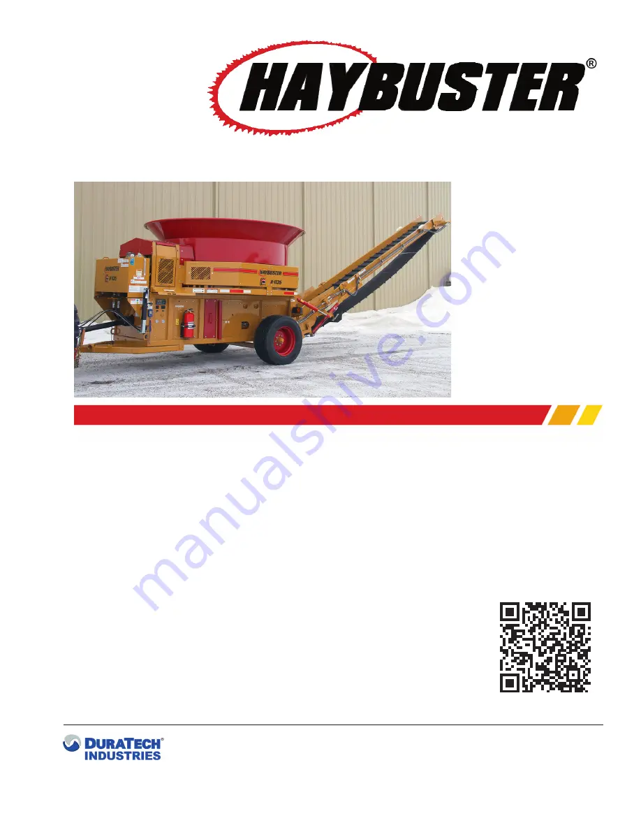
H-1135
PTO Driven Tub Grinder
Operating Instructions and Parts Reference
TM
P
roduct
I
nformatIon
Summary of Contents for H-1135
Page 2: ...A Tradition of Innovation Since 1966 ...
Page 4: ...A Tradition of Innovation Since 1966 ...
Page 62: ...52 H 1 1 3 5 T U B G R I N D E R O P E R A T I N G I N S T R U C T I O N S Lubrication Chart ...
Page 83: ...TM H 1135 PTO Driven Tub Grinder Part 2 Parts Reference 73 ...
Page 88: ...78 H 1 1 3 5 T U B G R I N D E R P A R T S R E F E R E N C E H I T C H A S S E M B L Y ...
Page 90: ...80 H 1 1 3 5 T U B G R I N D E R P A R T S R E F E R E N C E P L A T F O R M A S S E M B L Y ...
Page 96: ...86 H 1 1 3 5 T U B G R I N D E R P A R T S R E F E R E N C E R O T O R A S S E M B L Y ...
Page 98: ...88 H 1 1 3 5 T U B G R I N D E R P A R T S R E F E R E N C E P U M P D R I V E L I N E ...
Page 100: ...90 H 1 1 3 5 T U B G R I N D E R P A R T S R E F E R E N C E 3 6 0 0 9 0 7 D R I V E L I N E ...
Page 102: ...92 H 1 1 3 5 T U B G R I N D E R P A R T S R E F E R E N C E T U B D R I V E A S S E M B L Y ...
Page 104: ...94 H 1 1 3 5 T U B G R I N D E R P A R T S R E F E R E N C E T U B A S S E M B L Y ...
Page 122: ...112 H 1 1 3 5 T U B G R I N D E R P A R T S R E F E R E N C E A U X V A L V E H Y D V I E W A ...
Page 124: ...114 H 1 1 3 5 T U B G R I N D E R P A R T S R E F E R E N C E A U X V A L V E H Y D V I E W B ...
Page 126: ...116 H 1 1 3 5 T U B G R I N D E R P A R T S R E F E R E N C E A U X V A L V E H Y D V I E W C ...
Page 142: ...132 H 1 1 3 5 T U B G R I N D E R P A R T S R E F E R E N C E P R E S S U R E G A U G E S ...
Page 144: ...134 H 1 1 3 5 T U B G R I N D E R P A R T S R E F E R E N C E W H E E L S A N D H U B S ...
Page 146: ...136 H 1 1 3 5 T U B G R I N D E R P A R T S R E F E R E N C E O R B I T M O T O R ...
Page 154: ...144 H 1 1 3 5 T U B G R I N D E R P A R T S R E F E R E N C E E L E C T R I C A L P A R T S ...
Page 160: ...150 H 1 1 3 5 T U B G R I N D E R P A R T S R E F E R E N C E M I L L G R A T E 9 B A R 2 1 2 ...
Page 162: ...152 H 1 1 3 5 T U B G R I N D E R P A R T S R E F E R E N C E E A R C O R N K I T O P T I O N ...
Page 175: ...H 1135 TUB GRINDER PARTS REFERENCE FO 1 5701174 H 1135 MACHINE HARNESS ...
Page 176: ...H 1135 TUB GRINDER PARTS REFERENCE FO 2 5701170 PTO TUB TAIL LIGHTS HARNESS ...


