Harris NetWave, Operation & Technical Manual
The Harris NetWave Operation & Technical Manual is available for free download from manualshive.com. This comprehensive manual includes detailed instructions on operating and maintaining the Harris NetWave product. Download your copy today to ensure optimal performance and functionality of your device.
Share
Download


Reviews:
No comments
Related manuals for NetWave

GX300
Brand: Idex Pages: 29

HALO
Brand: Keeley Pages: 12

XL50-6GB
Brand: VAS Pages: 16

V5A TEDDY
Brand: Varimixer Pages: 8

VPM-1
Brand: Zeppelin Design Labs Pages: 28

20.0040
Brand: Monacor Pages: 14

Torpedo C.A.B.
Brand: Two notes Audio Engineering Pages: 28

BIGSBY
Brand: GameChanger Audio Pages: 8

Spectrum Enhancer SE200
Brand: Behringer Pages: 2

Mackie Control Universal Pro
Brand: Mackie Pages: 12

Boss PW-1
Brand: Boss Pages: 6

Magnolia Bakery M53
Brand: Hamilton Beach Pages: 24

COMET CHORUS
Brand: Maestro Pages: 38

LDSVIBZ24DC
Brand: LD Pages: 108

CX133
Brand: Cloud Pages: 10

FUZZ MFZ-271A
Brand: Maestro Pages: 8

PRINCIPIO DDI10142
Brand: Moulinex Pages: 49
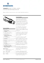
PENBERTHY CTE
Brand: Emerson Pages: 5


