Harris CM-30, Installation & Operation Manual
The Harris CM-30 is a high-quality industrial control monitor. Ensure your device is running optimally by referencing the Installation & Operation Manual. Download this manual for free from manualshive.com to understand the full capabilities and functions of this product. Keep your equipment in top shape with the user-friendly manual.
Share
Download


Reviews:
No comments
Related manuals for CM-30

DMM6500
Brand: Keithley Pages: 22

DMM6500
Brand: Keithley Pages: 99

3761
Brand: Keithley Pages: 25

USB-206
Brand: Humandata Pages: 15

DD230B
Brand: Dawson Pages: 13

CL1000
Brand: Klein Tools Pages: 6

AP33
Brand: Sanwa Pages: 2

VPU100
Brand: Quadra Plus Pages: 18

Gamma 20
Brand: Sifam Tinsley Pages: 16

61-310
Brand: IDEAL INDUSTRIES Pages: 15

3355
Brand: PeakTech Pages: 29

KM100
Brand: Kaiweets Pages: 21

7 function
Brand: Harbor Freight Tools Pages: 8

VA41
Brand: V&A Pages: 27

61-635
Brand: IDEAL INDUSTRIES Pages: 23

DDM190D
Brand: Dawson Tools Pages: 26
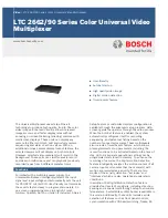
LTC 2662 Series
Brand: Bosch Pages: 3

AR6006
Brand: Robin Pages: 2


