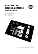
background image

CONTROLLER

HC2500 & HM1500

Instructionbook

679050- SW 1.52
GB - 07.2003

www.hardi-international.com

Summary of Contents for HC 2500 Series

Page 1: ...CONTROLLER HC2500 HM1500 Instructionbook 679050 SW 1 52 GB 07 2003 www hardi international com ...

Page 2: ... any responsibility for possible omissions or inac curacies in this publication although everything possible has been done to make it complete and correct As this instruction book covers more models and features or equipment which are available in certain countries only please pay attention to paragraphs dealing with precisely your model Published and printed by HARDI INTERNATIONAL A S We congratu...

Page 3: ...11 HM 1500 Changing the desired volume rate for alarm 11 HC 2500 Changing the volume rate 11 Menus 13 General keystroke 13 Keystroke menu tree chart 14 Main menu 15 Display readout 16 Tank contents 17 Calibration 18 Alarms 23 Sensor test 25 Area meter 26 Mistblowers and HM 1500 HC 2500 26 Storage 27 Emergency operation 27 Fault finding 27 Technical specifications 30 Chart for recording values 31 E...

Page 4: ...Variable figures PPU Pulses per unit For flow calibration The unit measure is litre UPP Unit per pulse For speed calibration The unit measure is metre PPR Pulses per revolution For revolutions calibration BK HARDI manual control unit BK EC HARDI manual control unit with electric on off and pressure regulation EVC or CB Electric control unit without main valve NOTE Text shown in square brackets or ...

Page 5: ... to clean the electronic components Press the keys with the underside of your finger Avoid using your finger nail If any portion of this instruction book remains unclear after reading it con tact your HARDI dealer or HARDI service personnel for further explanation before using the equipment Description The HARDI Monitor 1500 and HARDI Controller 2500 are for use in agricultural and horticultural p...

Page 6: ...y s memory and are not lost when the power is disconnected The materials and electronics for the components have been developed to last many years under agricultural conditions Options include a 4 20 mA transducer e g pressure revolutions transducer area meter transducer and switch box for boom sections when used with BK or BK EC control unit only for HM 1500 Fitting the system Please note the con...

Page 7: ...Flow transducer 7 Box connector socket 8 Spray control box HM 1500 Monitor with electric control unit EVC CB Active boom width is calculated automatically when the boom sections are operated NOTE Extended menu setting Control box is Connected ON OFF valve is Not present for EVC and CB Pressure system is No equalisation See Extended menu 1 HM 1500 display 2 Display connector plug 3 To 12 Volt power...

Page 8: ...transducer 6 Flow transducer 7 Box connector socket 8 Spray box for electric con trol unit 9 39 pin plug to control unit 10 Electric control unit Power supply The power supply is 12 Volt DC Brown wire is positive t Blue wire is negative Power supply must come directly from the battery The wires must have a cross sectional area of at least 1 0 mm2 to ensure sufficient power supply NOTE Do not conne...

Page 9: ...he mounting rod A is utilised to fit the display together with the Spray box Place Quick guide sticker at C NOTE Power must be disconnected before wire harness B is connected to the display The wire harness has identification labels D for different connections Connect up specific to your version ...

Page 10: ...d transducer for tractor Note the following if the speed transducer is fitted to the tractor or vehicle The speed transducer is an inductive type It requires a metallic protrusion e g bolt head to pass by it to trigger a signal A diode on the transducer will flash when a signal is detected Recommended distance between protrusion and transducer is 3 to 5 mm ...

Page 11: ...ransducer for BK and EVC control unit For BK and EVC control unit the housing is fitted just prior to the distribution valves Flow transducer is fitted to the housing and connected to the Scanbox with the a 3 poled plug ...

Page 12: ...he junction box circuit board Cables All the cables and wires must be routed so they do not get pinched snagged or melted NOTE An extension cable is available as an option if the computer is to be placed further away from the Spray control box Ref no 261933 NOTE Although the system meets standards EN 50081 1 1992 for generic emission and EN 50082 2 1995 for generic immunity some communication syst...

Page 13: ...g chosen volume rate To read the chosen volume rate press briefly either arrow keys on the display The chosen rate is shown The main picture will return again after 5 seconds or if you press accept key HM 1500 Changing the desired volume rate for alarm The desired rate must be entered if you wish to operate with the alarm Press either arrow keys on the display The rate per area is shown If the key...

Page 14: ...MAN over the displayed information Bottom line is cleared when MAN is displayed To go from manual to automatic dosage briefly touch the arrow key on the HC 2500 Reading and reset of area trip Area trip from 1 to 8 Y can be used for individual areas Area trip 0 is a tally of area trips 1 to 8 The treated area is memorised when the system is switched off 1 Press enter key for area covered and volume...

Page 15: ...e lower line in small letters displays the choices you have When the chosen menu is shown press the menu key again to open the menu When modifying a parameter prolonged pressure on the arrow key will gener ally cause the data shown on the display to alter faster After the parameter is modified press the accept key The display then changes back to the previous picture Press the accept key until the...

Page 16: ... rate Optional sensor Revolutions Speed Active boom size Flow calibration Speed calibration Revolutions Boom sections size Volume rate Tank Area 0 to 8 Flow Speed Area switch test Revolutions Optional sensor Keystroke menu tree chart Press to read or alter HC 2500 chosen volume rate Press to read or reset area trip Main menu ...

Page 17: ...ay readout Main menu The upper line will read MAIN MENU The lower line displays the choices To choose what is to be displayed on screen To change the indicated tank contents To access calibration menus To set alarm parameters To select register to record or read area covered and volume sprayed To test that the transducers function ...

Page 18: ...per or lower line of the display To choose where to show information Press arrow key to move Show here from the upper to lower line Press menu key to continue The upper line will read DISPLAY READOUT The lower line displays the choices To show the actual application rate To show the programmed and actual application rate To show the tank contents If two tanks are used the tank contents is the tota...

Page 19: ...x x x x L To show readout from optional analog transducer To show revolutions To show driving speed To see the active boom size Tank contents If the sprayer is partially refilled or refilled the tank contents can be adjusted See Extended menu to set tank size Press menu key and use arrow keys to raise or lower value ...

Page 20: ... work width for each boom section is necessary to calculate dosage and area covered Method 1 Use arrow key to set number of boom sections and press menu key Maximum number of sections is 8 Press menu key to continue For mistblowers number of sections is typically 2 2 Use the arrow key to increase or decrease section work width Press menu key to continue to next boom section After the last section ...

Page 21: ...ansducer Calibration is recommended to be carried out at least once during the spray ing season Use the chart at the back of the book to record the values Flow constant To change the flow constant theoretically During theoretical flow calibration the number of pulses per unit are shown on the display For example 120 0 PPU indicates the number of pulses which theoreti cally come from the flow trans...

Page 22: ... of nozzles is set with the arrow key to read the actual number of nozzles to spray Press the menu key to continue 2 Open all boom sections and if fitted close end nozzle 3 Set the main ON OFF to ON The display unit will then show the individual nozzle output per minute 4 Using a HARDI calibration jug check the actual nozzle output per minute It is recommended that an average of several nozzles be...

Page 23: ...y dosed Method 1 Place the tank on level ground and fill up with water until the level reaches a unique mark on the tank contents level indicator e g 1000 litres 2 Open all boom sections and if fitted close end nozzle 3 Open menu and set the main ON OFF to ON 4 Engage the P T O The display unit will then begin to count the volume being emptied through the nozzles 5 When for example 600 litres have...

Page 24: ... UPP is the distance in metre on the circumference of the wheel between magnets For example if the wheel circumference is 2 00 m and 4 magnets are fitted UPP is 0 5000 Speed practical Practical calibration of speed is done by driving a measured distance and cor recting the display so that the actual and the calculated distances are the same Theoretical speed calibration should be carried out befor...

Page 25: ...rrect the distance shown on the display with the arrow key to read the actual distance Revolutions calibration For calibration of revolutions transducer The constant pulse per revolution PPR is the number of pulses for one revolution For example if one magnet is fitted the PPR is 1 0 Alarms There are 2 alarms a tank alarm for low tank contents and a volume rate alarm for over or under application ...

Page 26: ... key Volume rate alarm for over or under application for more than 20 seconds Suggested setting is 5 For no alarm set at 0 The beeper can be activated on or de activated off by pressing the arrow key Area volume trip It is possible to choose up to 9 area trip meters 0 to 8 Area 0 is a total for all areas treated When any of the other areas are used the treated area and volume will also be register...

Page 27: ...except for the optional analog transducer that is read in milli ampere Follow instruc tions on the display To test the flow sensor Remove transducer from flow housing and spin rotor Every second magnet will give a count indicating correct function See also Testing flow transducer To test the speed sensor Every magnet will give a count indicating correct function See also Testing speed transducer T...

Page 28: ... side of the magnet or metal lic protrusion is located directly in front of the transducer the area meter will stop registering area When using a HM 1500 with manual control unit and Spray box or HC 2500 with Spray control box all the switches must be turned on If you do not want to utilise the area meter transducer the main on off switch can be used to start and stop the area register Mistblowers...

Page 29: ...splayed area larger Field was not rectangular than actual area Tramlines narrower than Measure tramline width spray width Displayed volume larger Pressure equalisation valve Replace seals than actual volume leaks Fine tuning the flow constant PPU Calibration of the flow transducer is carried out with clean water but small changes may occur when adding pesticides or fertiliser This will effect the ...

Page 30: ...ve 1 Check the rotor turns freely 2 Each vane in the rotor has a magnet in it with the pole facing out Check that the 4 magnets are present 3 Check every second magnet has the same pole orientation so the rotor magnets are N S N S 4 Connect negative from multimeter to nega tive of battery 5 Set multimeter to DC volt 6 By turning the mill wheel slowly this will register approx 8 0 1 volt with the d...

Page 31: ...r to DC volt For inductive type 3 Bring a metallic object 3 to 5 mm up to the transducer This will register 1 4 0 2 volt and the diode will turn on 4 By removing the object this will register 12 0 1 0 volt Diode is off For Hall element type with magnet 3 By bringing the south pole of a magnet dis tance 5 mm 2 mm by the transducer this will register 0 3 0 1 volt 4 By removing the magnet this will r...

Page 32: ...rifice PPU identification l min mm value S 67 One outside groove 5 150 13 5 120 00 S 67 No groove 10 300 20 0 60 00 S 67 Two outside grooves 35 600 36 0 125 00 Pressure drop over 13 5 mm orifice is 1 bar at 150 l min Packaging information Materials used for packaging are environmentally compatible They can be safely deposited or they can be burnt in an incinerator Recycling Cardboard Can recycle u...

Page 33: ...em To select pressure system Equalisation No equalisation Control box To indicate control box connection Lunch box Spray box Not connected To July 2003 Lunch box indicates rectangular control box From Aug 2003 Spray box indicates wave shaped control box Tank volume max To pre set tank volume indicated at start up Analog adjust To calibrate the optional transducer max min offset in mA Analog unit t...

Page 34: ...ure system Equalisation Equalisation Control box Lunch box Not Connected Tank size 2000 l 2000 l Analog adjustment max 10 max 10 min 0 min 0 offset 0 mA offset 0 mA Analog unit text Bar Bar Regulation con 0 0 Duty cycle 10 Not relevant Flow PPU 120 0 120 0 Speed UPP 1 0000 1 0000 HC 2500 For EVC or CB control unit set ON OFF valve to Not present HM 1500 For BK or BK EC control unit with switch con...

Page 35: ...eclare that the following product Adhere extra shipping package labels to inside cover was manufactured in conformity with the provisions in the EMC directive 89 336 EEC EN 50081 1 1992 generic emission and EN 50082 2 1995 generic immunity Taastrup 2 07 2003 Lars Bentsen Product Development Manager HARDI INTERNATIONAL A S ...

Page 36: ...34 26000700 Spare parts ...

Page 37: ...35 ...

Page 38: ...36 Notes ...

Reviews: