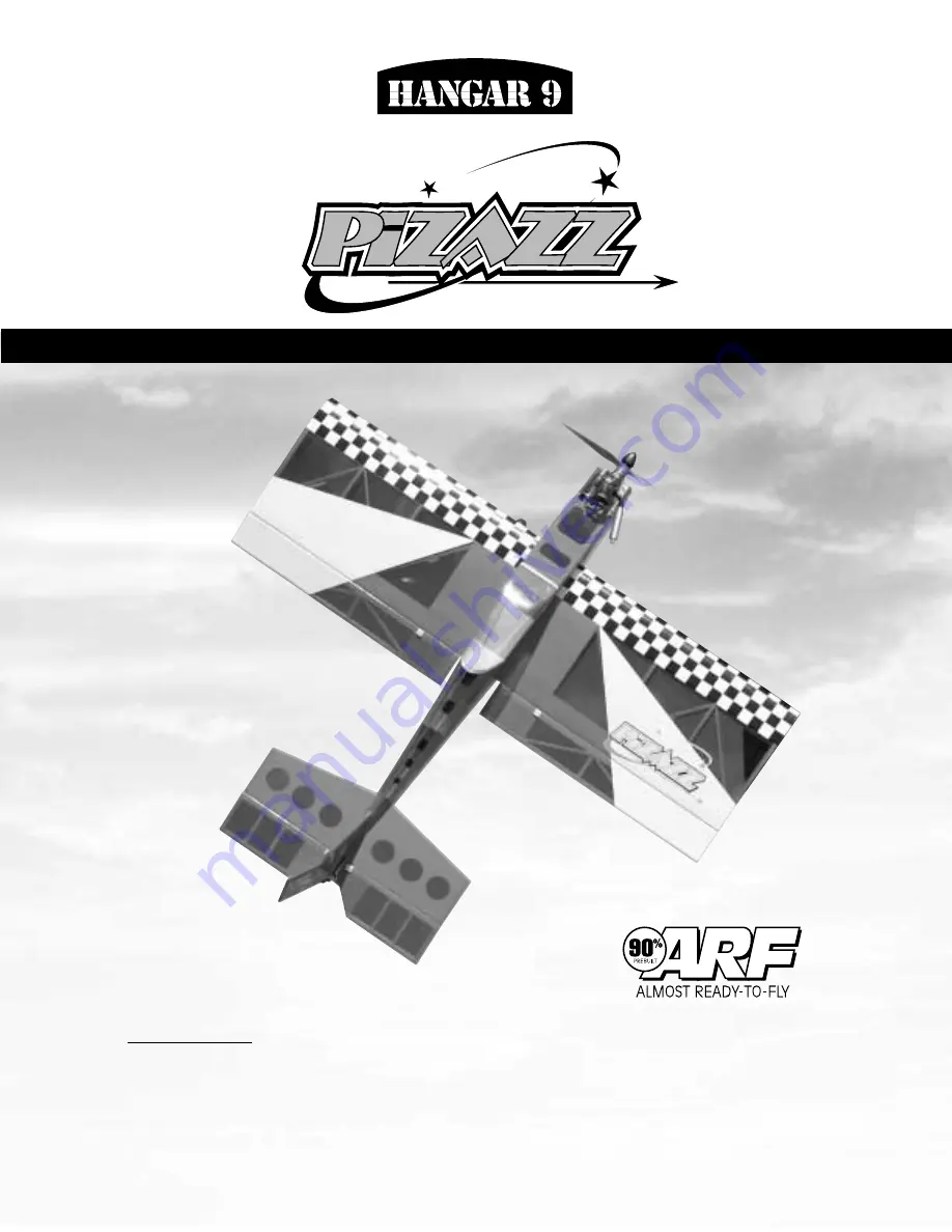
background image

INSTRUCTION MANUAL

Specifications:

• Wingspan: ............................................................................................................ 48 in (1219 mm)
• Overall Length: ................................................................................................... 48 in (1219 mm)
• Wing Area:................................................................................................ 725 sq in (46.8 dm sq)
• Weight (Approx.): ................................................................................. 4.5-5.5 lbs (2.0-2.5 kg) 
Recommended Engines:

2-Cycle: .40-.58
4-Cycle: .50-.72 

• 90% prebuilt
• Hardware included  
• Precovered with Hangar 9

UltraCote

®

• Incredible 3-D/fun-fly performer

WE GET PEOPLE FLYING

TM

TM

TM

Summary of Contents for PiZAZZ

Page 1: ... Length 48 in 1219 mm Wing Area 725 sq in 46 8 dm sq Weight Approx 4 5 5 5 lbs 2 0 2 5 kg Recommended Engines 2 Cycle 40 58 4 Cycle 50 72 90 prebuilt Hardware included Precovered with Hangar 9 UltraCote Incredible 3 D fun fly performer WE GET PEOPLE FLYING TM TM TM ...

Page 2: ... especially useful for flapperon configuration of the control surfaces This configuration offers excellent slow speed and stall characteristics that allow even inexperienced pilots to feel at home Plus it offers aerobatic capabilities that will have your flying buddies drooling To get the most out of your Pizazz we strongly suggest using a computer radio system This allows you to explore the vario...

Page 3: ...prototype 4 MDSE058 SAIE072 Tools and Supplies Needed not included in kit Adhesives Thin CA cyanoacrylate glue Medium CA cyanoacrylate glue Thick CA cyanoacrylate glue CA remover debonder Masking tape 6 minute epoxy 30 minute epoxy 242 threadlock blue threadlock Tools Drill Drill Bit 1 16 3 32 1 8 Medium Phillips screwdriver Z bend pliers Needle nose pliers Hobby knife with 11 blade Mixing sticks ...

Page 4: ... Fuselage HAN2152 3 Tail Set HAN2153 4 Canopy HAN2154 5 Landing Gear HAN2155 6 Wheels 2 1 2 7 Pushrods 8 Fuel Tank 8 oz 9 Tail Wheel Assembly HAN2087 10 Tail Wheel 1 1 4 11 Nylon 2 56 Clevis 5 12 Nylon Control Horns 5 13 Main Wheel Axles 1 2 3 4 5 6 7 8 9 10 11 12 13 ...

Page 5: ...stablish the center line of the wing and mark with a pen or pencil Step 2 Carefully slide the wing into the fuselage opening the servo openings in the wing should face the bottom of the fuselage as shown Do not force the wing as you may crush the structure Some trimming may be required You want a fairly snug fit but not at the expense of crushing the wing structure Step 3 Measure the distance the ...

Page 6: ... the fuselage and are sure it is centered mix up approximately 1 ounce of 30 minute epoxy Step 5 Apply the epoxy to both sides of the wing center top and bottom To apply epoxy to top slide wing off center and apply epoxy from outside of fuselage on both sides Slide the wing back and forth to work epoxy into the joint of the wing fuselage Step 6 Wipe away excess epoxy with rubbing alcohol and a pap...

Page 7: ... left aileron onto the wing until there is only a slight gap The hinge is now centered on the wing panel and aileron Remove the T pin and snug the aileron against the wing panel This will ensure that the hinges are centered Step 5 Deflect the aileron and completely saturate the hinge with thin CA glue The aileron s front surface should lightly contact the wing during this procedure Ideally when th...

Page 8: ...area Step 8 Repeat this process with the right aileron securely hinging the aileron in place Step 9 After both ailerons are securely hinged firmly grasp the wing and each aileron to check that the hinges are securely glued and cannot be pulled apart To do this apply medium pressure while trying separating the aileron from the wing using caution to be certain you don t crush the wing structure Move...

Page 9: ...side the wing Step 2 Trial fit the servo into the servo opening Depending upon the type of servo installed some trimming may be required Note that the servo is orientated so the servo arm is closer to the trailing edge of the wing Step 3 With the servo in place mark the location of the servo screws and then remove the servo Step 4 Using a 1 16 drill bit drill the servo screw locations marked in St...

Page 10: ...re for the other aileron servo Note It is recommended to have each servo connected to a separate channel in the receiver if your radio system has flap compatibility This will allow for flaperon function Please refer to your radio system operating instructions for selection of the flaperon wing pro gram so you can set up the Pizazz control surfaces for this feature ...

Page 11: ...moved to their electrical center you can position the servo control arm so that it will be approximately 90 degrees to the linkage when it s attached It s important that the mechanical adjustments are made as closely as possible before attempting to make any electrical adjustments through the transmitter programs Step 3 The control horn should be positioned so the holes that the clevis connects on...

Page 12: ...trol surface and hold the linkage wire directly over the elec tronically centered servo arm Place a mark on the rod directly over the hole second hole from the end of arm in servo control arm that it will connect too Step 8 Make a Z bend in the rod at the location you just marked Step 9 Insert the Z bend through the second hole from the end of the servo arm Install the clevis back onto the control...

Page 13: ... saddle cut out for the horizontal stabilizer and vertical fin to be mounted Use a sharp hobby knife to remove the trim from the slots in the fuselage Make a center mark on the front of the saddle on the fuselage and place the horizontal stabilizer into the horizontal stabilizer saddle Align the two marks you just made Tape the leading edge and trailing edge of the horizontal stabilizer to the fus...

Page 14: ...abilizer are not parallel carefully trim the horizontal stabilizer saddle to adjust as necessary Step 8 Mix approximately 1 2 ounce minimum of 30 minute epoxy to install the horizontal stabilizer to the fuselage Using an epoxy brush or mixing stick spread the epoxy onto the bottom of the horizontal stabilizer where it comes into contact with the fuselage Also coat the stabilizer saddle area that w...

Page 15: ...r should not be hinged to the horizontal stabilizer at this time It will be attached later Step 3 Mark the vertical stabilizer on both sides where it exits the fin blocks Step 4 Remove the vertical stabilizer and carefully cut away the covering with a sharp hobby knife just inside the lines you marked in Step 3 Caution Do not cut into the wood of the vertical stabilizer when cutting the covering a...

Page 16: ...17 Step 7 Using a 90 degree triangle make sure the fin is perpendicular to the horizontal stabilizer Use masking tape to hold the vertical stabilizer in place until the epoxy cures ...

Page 17: ... 42 Petroleum jelly or oil Masking tape Step 1 Insert the hinges into the precut slots of the rudder do not glue at this time and install the rudder onto the vertical stabilizer Step 2 Locate the tail wheel assembly It includes the tail wheel wire black nylon bearing tail wheel wheel collar and screw Step 3 Use needle nose pliers or equivalent to bend a 90 degree bend in the tail wheel wire Rememb...

Page 18: ...e tail wheel assembly turns freely with the rudder Step 9 When you re satisfied with the fit remove the tail wheel assembly and rudder from the fuselage Reinstall the hinges in the rudder using T pins to make sure the hinges are centered as described in Section 1 Step 10 Mix approximately 1 4 ounce of 30 minute epoxy and apply it both to the nylon bearing where it goes into the fuselage and into t...

Page 19: ...fit the elevator into the proper position on the horizontal stabilizer using the same hinging technique used in Section 2 Remember to remove the T pins before applying the CA glue Also make sure the tail wheel is free to move its full range Step 2 With one elevator half aligned left and right apply thin CA glue to the hinges on both sides Wipe away any excess CA with CA remover debonder and a pape...

Page 20: ... over 1 2 on the inboard side of the elevator half Mark the elevator as shown with a felt tipped pen or a pencil This mark will be the center of the elevator control horn location Repeat for the other elevator half Step 2 Place the center of the control horn on the elevator at the mark made in the previous step Mark the hole positions of the control horn with a felt tipped pen or pencil Step 3 Rem...

Page 21: ...as the center for the rudder control horn Step 7 Center the control horn over the mark you ve just made Make sure the horn is positioned over the hinge line just like you did for the elevator Using a felt tipped pen or pencil mark the mounting hole locations onto the rudder Step 8 Drill these holes with a 1 16 drill bit and install the rudder control horn using the screws and backplate provided ...

Page 22: ... on one side of the black stopper so the small peg faces away from the stopper toward the inside of the fuel tank The larger cap is placed on the other side of the rubber stopper so that the raised center faces away from the rubber stopper Step 4 Locate the other long tube and bend it using your fingers as shown This tube will be the vent tube connected to the pressure fitting on the engine muffle...

Page 23: ...lack cap on the other side of the rubber stopper Step 10 Carefully insert the assembly into the fuel tank Note the position of the vent tube It must be at the top portion of the fuel tank to function properly Make sure the clunk fuel pickup is free to move as the aircraft changes attitude If it is too short it may flip forward and kink the fuel line when the aircraft makes violent maneauvers ...

Page 24: ...es Needed Phillips Screwdriver or Hex wrench Drill Drill Bit 1 8 Threadlock Step 1 Locate the two engine mounts and hardware Step 2 Place the engine mounts as shown in the front of the fuselage Trial fit the engine in place Using a pencil mark the position of the four holes that secure the mounts to the fuselage as shown Section 11 Installing the Engine ...

Page 25: ...ired position It is helpful to have the prop and spinner installed at this time to check the clearance Using a pencil carefully mark the engine mount through the holes in the engine mount flange Remove the engine and drill four 1 8 holes where marked Step 7 Secure the engine in place using the four remaining screws nuts and washers Step 8 Install the muffler per the instructions included with the ...

Page 26: ... E Elevator Screw the servos in place using the 12 servo screws included with the servos Step 2 Use radio packing foam not included available at your local hobby shop when you install the receiver and battery Step 3 Be sure to attach the servo leads to the receiver prior to installing the receiver into the fuselage refer to Radio Set Up section Route the antenna outside the fuselage back to the st...

Page 27: ... from the opening Step 6 Using a 1 16 drill bit drill two mounting holes for the switch and two for the charge jack as marked Using your hobby knife carefully cut out the opening for the switch between the screw holes Step 7 Reposition the switch plate as shown and place the switch on the inside of the fuselage Using the two screws supplied with the switch attach the switch to the fuselage Plug in...

Page 28: ...ual sections Step 3 Locate the components for the elevator control linkage made up of a wooden pushrod two threaded 10 and one un threaded 6 control wires two clevis two clevis keepers 7mm pcs of fuel tubing not included two pieces of nylon thread and two pieces of heat shrink tubing Since the Pizazz uses a split elevator you will construct a Y pushrod that has two threaded rods on one end of the ...

Page 29: ...to the holes of the wood pushrod without the ends extending out of the hole on the other side Step 9 Using the pattern shown below as a reference bend the two threaded 10 rods the approximate angle the diagram shows These are only approximate final adjustment will be made when fitting the control rods to each elevator control horn Step 10 Trial fit the two 10 threaded rods into the holes on either...

Page 30: ... the hole previously drilled in Step 5 Step 15 With the clevis attached to the elevator control horns you are ready to measure the rod end that will attach to the elevator servo arm Positon the wire rod over the elevator servo arm electrically centered hole that is the outermost hole Mark with a pencil or felt tipped pen This is where you will make the Z bend to go into the elevator servo arm hole...

Page 31: ...p 19 Continued Note The servo arms and pushrods should approximate a 90 degree angle Be sure to use sections of fuel tubing over each of the clevis to make sure they do not open accidentally Step 20 The sequence of installing the throttle pushrod in this manual is for most engines Installation may slightly vary depending on the type brand of engine you use to power your Pizazz Step 21 Locate the 1...

Page 32: ...24 Adjustments to the throttle barrel opening can be made by threading the clevis in or out Use a small piece of fuel tubing over the clevis to help prevent it from opening Step 25 Turn on your radio system and center your transmit ter s throttle stick and trim and center your throttle servo arm Adjust until the throttle arm of your engine is 1 2 open closed Step 26 With your radio system on and t...

Page 33: ...carefully remove the covering over the predrilled holes Step 3 Bolt the landing gear onto the fuselage with the included hardware Take a bolt and washer and insert it through the aluminum landing gear and holes in hatch To access the radio compartment remove the landing gear and hatch Thread the mounting bolts into the preinstalled blind nuts and securely tighten Note It is a good idea to use thre...

Page 34: ...Section 16 Control Throw Recommendations Section 17 Balancing the Pizazz An extremely important step in preparing an aircraft for flight is ensuring it is properly balanced Do not neglect this step Each individual s Pizazz will not be the same because of the various combinations of engines that can be used servos radio equipment type of hardware used and assembly methods used during building of th...

Page 35: ...This is accomplished by turning on your transmitter with the antenna collapsed Turn on the radio in your airplane With your airplane on the ground you should be able to walk 30 paces away from your airplane and still have complete control of all functions If not don t attempt to fly Have your radio equipment checked out by the manufacturer 2 Double check that all controls aileron elevator throttle...

Page 36: ...ls while being flown indoors 8 I will not operate models with metal bladed propellers or with gaseous boosts in which gases other than air enter their internal combustion engine s nor will I operate models with extremely hazardous fuels such as those containing tetranitromethane or hydrazine 9 I will not operate models with pyrotechnics any device that explodes burns or propels a projectile of any...

Page 37: ...s and contestants must properly wear helmets which are OSHA DOT ANSI SNELL or NOCASE approved or comparable standard while on the race course All officials will be off the course except the starter and his her assistant On the course is defined to mean any area beyond the pilot staging area where actual flying takes place B I will not fly my model aircraft in any organized racing event which does ...

Page 38: ...NOTES 39 ...

Page 39: ... Copyright 2001 Horizon Hobby Inc 217 355 9511 www horizonhobby com ...

Reviews: