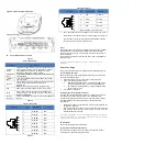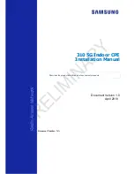
HAN AP321 and AP321e
Installation Guide
Summary of Installation Steps
•
WLAN Planning. Usually, a comprehensive site survey is required
before installation, such as installation location, brackets, cables,
power source, etc.
•
Unpack the AP box and check all contents
•
Install the AP bracket on ceiling or wall
•
Installing the AP
•
Connecting required cables
•
Power connection
•
Verifying post
-
installation connectivity
•
AP provisioning
Access points are radio transmission devices and are subject to
governmental regulation. Network administrators who are responsible
for the configuration and operation of access points must comply with
local broadcast regulations. Specifically, access point must use channel
assignments appropriate to the location where the access point will be
deployed.
Package Contents
Item
Name
Qty
Unit
1
Access Point
1
Pcs
2
Quick Start Guide
1
Pcs
Installation Guide
1
Pcs
Regulatory Compliance and Safety
Information
1
Pcs
User Guide Info Card
1
Pcs
◆
Optional Accessories
(
To be ordered separately
)
Item
Name
Description
1
OAW
-
AP
-
MNT
-
B
Indoor mounting kit, Type B1(9/16") and
B2(15/16") for T shaped ceiling rail.
2
OAW
-
AP
-
MNT
-
C
Indoor mounting kit, Type C1(Open
Silhouette) and C2 (Flanged Interlude),
for other shaped ceiling rail mounting.
3
OAW
-
AP
-
MNT
-
W
Indoor mounting kit, Type W wall and
ceiling mounting with screws.
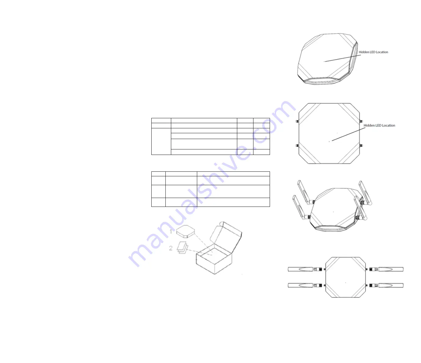
Figure1: Product Packing
Inform your HAN sales representative of incorrect, missing, or
damaged parts. If possible, retain the carton, including the
original packing materials. Use these materials to repack and
return the unit to the supplier if needed. Additional mounting
kits for use with the AP321 series access points are sold
separately. Contact your ALE sales representative for details.
Hardware Overview
The following sections outline the hardware components of the AP321
and AP321e Series access point.
Figure 2: AP321 Front View
Figure 3: AP321e Front View
Figure 4: AP321e Include Antennas Front View
Figure 5: Install the external antenna on AP321e.
◆
The external antennas is sold separately.
LED
The AP321 and AP321e access point is equipped with hidden LED display
that indicates different status with different color.
For the details of the LED status, please refer to the Quick Start Guide.


