


This manual describes how to use the following products:
SC900AX Lithium/lithium 1-button 1-home doorphone kit
SC901AX Mains/mains code-operated 1-home doorphone kit
SC902AX Mains/lithium 1-button 1-home doorphone kit
SC903AX Lithium/mains code-operated 1-home doorphone kit
SC100AX Interior handset unit + base + EU power pack
SC101AX Interior handset unit + battery-charging base
SC200AX Mains-powered controller
SC201AX Lithium battery-operated controller
MHF01X
Translucent 2-home outdoor caller unit
MHF02X
Translucent code-operated 2-home outdoor caller unit
MHF03X
Opaque 1-home outdoor caller unit
MHF04X
Opaque 2-home outdoor caller unit
MHF05X
Opaque code-operated 1-home outdoor caller unit
MHF06X
Opaque code-operated 2-home outdoor caller unit
The doorphone system can be used to welcome and filter visitors, listen in to background sounds
at each access point and communicate with another handset.
It can also be used to remotely control:
• one or several electrical latches,
• one or several automatic gate control systems,
• one or several automatic garage door control systems,
• one or several lights.
It also allows users to check the status of access points or lights using the screen on the handset
at any time.
Several additional interior handset units can be added to the doorphone system (maximum of 4
per call button).
212
GB
Foreword
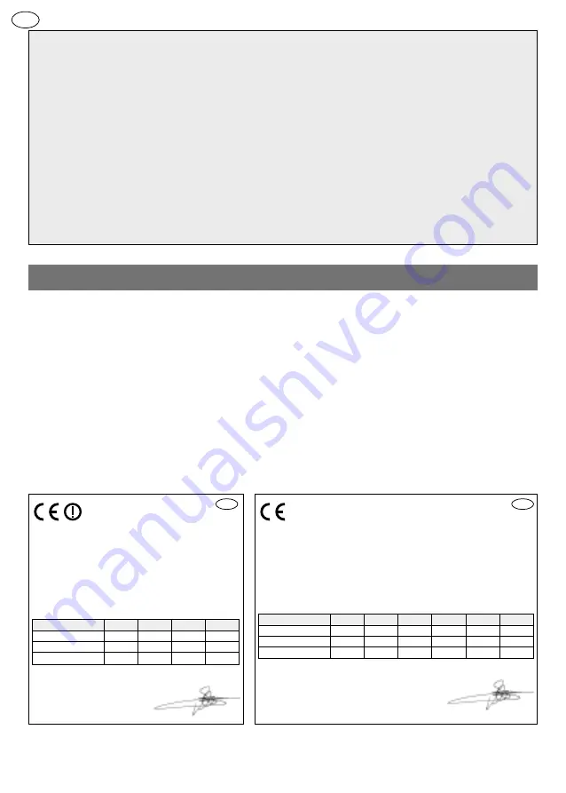
DECLARATION OF CONFORMITY
Manufacturer:
Hager Security SAS
Address:
F-38926 Crolles Cedex - France
Product type:
Doorphone
Trade mark:
Daitem
We declare under our sole responsibility that the products to which
this declaration relates are compliant with the essential requirements
of the following directives:
• R&TTE Directive: 99/5/CE
• Low Voltage Directive: 2006/95/CE
• ROHS directive: 2002/95/CE
in compliance with the following harmonised European standards:
These products can be used in all EU and EEA countries and Switzerland.
Crolles, 06/05/10
Signature: Patrick Bernard
Research & Development Director
10
GB
10
GB
Product reference
MHF01X MHF02X MHF03X MHF04X MHF05X MHF06X
EN 300 330-2 V1.3.1
X
X
X
X
X
X
EN 60950 (2006)
X
X
X
X
X
X
EN 301 489-1 V1.8.1
X
X
X
X
X
X
DECLARATION OF CONFORMITY
Manufacturer:
Hager Security SAS
Address:
F-38926 Crolles Cedex - France
Product type:
Doorphone
Trade mark:
Daitem
We declare under our sole responsibility that the products to
which this declaration relates are compliant with the essential
requirements of the following directives:
• R&TTE Directive: 99/5/CE
• Low Voltage Directive: 2006/95/CE
• ROHS directive: 2002/95/CE
in compliance with the following harmonised European
standards:
These products can be used in all EU and EEA countries and
Switzerland.
Crolles, 06/05/10
Signature: Patrick Bernard
Research & Development Director
Product reference
SC100AX SC101AX SC200AX SC201AX
EN 300 220-2 V2.1.2
X
X
X
X
EN 60950 (2006)
X
X
X
X
EN 301 489-1 V1.8.1
X
X
X
X
Non-binding document, subject to modification without notice.
Summary of Contents for SC901AX
Page 19: ...4 Pozidriv 2 6 3 5 230 GB ...
Page 20: ...7 8 9 3 5 231 GB ...
Page 71: ...282 ...
Page 72: ...283 ...


