background image

Montageanleitung
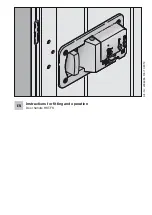
Mounting Instructions
Instructions de montage
Istruzioni di montaggio
Instrucciones de montaje

Dialock Türterminal DTSH, DTSH FH

Dialock Door Terminal DTSH, DTSH FH

Dialock Terminal de Porte DTSH, DTSH FH

Dialock Terminale Porta DTSH, DTSH FH

Dialock Terminal de Puerta DTSH, DTSH FH

EN

FR

IT

ES

DE

Summary of Contents for dialock DTSH

Page 1: ... montage Istruzioni di montaggio Instrucciones de montaje Dialock Türterminal DTSH DTSH FH Dialock Door Terminal DTSH DTSH FH Dialock Terminal de Porte DTSH DTSH FH Dialock Terminale Porta DTSH DTSH FH Dialock Terminal de Puerta DTSH DTSH FH EN FR IT ES DE ...

Page 2: ...of delivery 39 Accessories not included in the scope of delivery 40 DTSH Application areas 42 DTSH FH application areas 42 Features 42 Installation instructions 43 Start up 63 Short instructions 65 Operation 66 Battery change 66 Emergency opening 68 FAQ 69 Maintenance and cleaning instructions 69 Technical data 69 ...

Page 3: ...38 English Dialock Door Terminals DTSH DTSH FH Status 07 2008 732 29 134 Installation Instructions ...

Page 4: ...rt up and maintenance guide when starting up assigning keys Scope of delivery 1 External module 1 Internal module Small parts bag with profile cylinder cover break open seal 1 Promaseal strip DTSH FH only Profile cylinder cover Fig 1 Profile cylinder cover Rotary knob fixed at hood Internal module External module Fig 3 Promaseal strip Fig 2 ...

Page 5: ...Optional Stainless steel matt Stainless steel polished Brass polished 25 pieces 917 90 483 917 90 480 917 90 481 917 90 488 User key Different models 4 x 1 5 V batteries size AA Mignon type E91 Energizer Ultra 910 54 980 Lever handle aperture part Different models DTSH FH Only supplied models may be used see catalogue Single profile cylinder Length depends on door leaf thickness Single profile cyl...

Page 6: ... M4x40 for DTSH FH 917 90 122 3 57 67 mm 1 inner square spindle L 120mm 917 90 246 4 countersunk head screws DIN 965 M4x50 for DTSH FH 917 90 124 4 67 77 mm 1 inner square spindle L 130mm 917 90 248 4 countersunk head screws DIN 965 M4x60 for DTSH FH 917 90 126 5 77 87 mm 1 inner square spindle L 130mm 917 90 250 4 countersunk head screws DIN 965 M4x70 for DTSH FH 917 90 128 6 87 97 mm 1 inner squ...

Page 7: ...the doors Please contact your Häfele sales office if you intend to use the door termi nal on fire resistant and smoke control doors DTSH FH application areas Permission from the door manufacturer is required to install the DTSH FH If the DTSH FH door terminal is installed without permission the Fire Cer tificate for the fire resistant and smoke control door will be invalidated The fitting must alw...

Page 8: ...rtise lock The mortise lock must have the depicted Mortice lock bolt through fixing holes for the fitting Fig 4 The length of the following Dialock DTSH door terminal components depends on the thickness of the door leaf They must therefore be selected accordingly Mounting set consisting of Fixing screws and inner square spindle for scope of delivery see page 39 Single profile cylinder not included...

Page 9: ...8 732 29 134 Installation Instructions The black plastic profile cylinder cover is also a break open seal and must not be fitted until start up has taken place Do not bring media keys into the reading area during installation if the batteries have been inserted ...

Page 10: ... inner hood 006 32 013 DTSH DIN drilling jig 917 90 005 Router cutter for breakthrough to lock nut Ø 25 mm 910 54 995 Router cutter with centring pin only needed for mortise lock with mergency open ing logging Fig 5 Ø 32 mm 910 54 997 Stop for router cutter only needed for mor tise lock with emer gency opening log Fig 6 32 mm 001 28 129 Drill bits cable leadthrough Fig 7 13 mm 001 41 351 Drill Fas...

Page 11: ...llowing procedure when installing the Dialock DTSH door terminal Insert mortise lock A Page 47 Drill holes for fixing screws and connecting cable B Page 48 Remove mortise lock clean and re insert C Page 53 Insert single profile cylinder D Page 54 Adjust external module for right pointed left pointed door E handle Page 56 Secure inner square spindle F Page 57 Mount external module of Dialock DTSH d...

Page 12: ...ck 1 Fig 9 cable Fig 10 cable Fig 11 Hooded screw Fig 12 Screw in the mortise lock 2 With mortise lock with emergency opening log the mortise lock con necting cable must be fixed in position as shown in fig 11 Check position of mortise lock using a locking cylinder The locking cyl 3 inder must be easy to insert If necessary increase size of lock pocket or clear the locking cylinder access route in...

Page 13: ...be part drilled from one side of the door to the middle of the door leaf and then drilled through from the other side of the door Preparing for drilling Without emergency opening log Drilling pattern without emergency opening log Fig 13 Cable drill hole Ø 13 mm continuous for connecting cable for external internal module Depth cutting Ø 25 mm external only 7 mm deep 4 x fixing holes Ø 8 mm continu...

Page 14: ...tions Depth cutting only needed for Fig 14 emergency opening log Depth cutting to lock pocket Ø 32 mm Centring hole for router cutter with centring pin Space for coupling Inside of door Outside of door Section Drilling pattern with Fig 15 emergency opening logging Only for emergency opening log ...

Page 15: ...t A through the square spindle and cylinder apertures of the mor tise lock Fig 16 Place drilling jig part B onto the 3 centring pins from the other side of the door Clamp drilling jig into position using a screw clamp Drilling jig parts A C Fig 17 Do not damage surface of door Use drilling jig The drilling jig consists of parts A B and C The drilling template must be prepared in combinations A B a...

Page 16: ...as far as the middle of the door leaf using the 8 mm drill bit Drill 13 mm hole at both sides for cable connection Fig 20 Fig 21 Cut out the coupling area Note Cutting only required on the out side Do not damage mortise lock with router cutter Slide the spacer onto the journal of the router cut ter to prevent damage Fig 20 21 Spacer 25 mm router cutter 25 mm router cutter Spacer ...

Page 17: ...e of the door leaf from both sides using the 8 mm drill bit to connect the emergency opening log Centring hole for 32 mm router cutter This procedure can destroy the connecting cable for emergency opening log The con necting cable must not be routed in the lock pocket at location A fig 22 Fig 23 Remove mortise lock from lock pocket Depth cutting as far as lock pocket Page 49 fig 15 section A A A ...

Page 18: ...e continuing remove debris and clean lock pocket With emergency opening log lead con necting cable into the inside of the lock pock et and out via the hole that has been cut Fig 25 Pay attention to cable routing when inserting the connecting cable Do not crush cable Fig 25 Insert mortise lock as described in A Insert mortise lock on page 47 Connection cable Depth cutting Door leaf Connector Mortis...

Page 19: ...file cylinder and the lock Do not use force Only use one single profile cylinder with the correct length See fig 26 A a1 a2 External fitting Door leaf Single profile cylinder Forend screw Important when ordering A a1 a2 a1 inner fitting height Recess in fitting for single profile cylinder at least 19 mm to a maximum of 24 mm a2 Distance between middle of forend screw and door leaf surface Fig 26 ...

Page 20: ...file cylinder must be used with emergency opening log The length of the forend screw should not exceed the backset max 10 mm otherwise the emer gency opening log sensor may be destroyed Slide single profile cylinder into door lock until forend 1 screw can be screwed in from the edge of the door Check whether the follower locking lug rotates smoothly when the key is turned Otherwise correct the pos...

Page 21: ...nal module so that the direction of movement matches the application Fig 30 Right pointed door handle zero position Fig 31 Left pointed door handle leftside zero position Rotate outer square spindle with lever handle aperture part to upper 1 stop position zero position and hold Gently knock pin 3 x 24 mm into the hole marked R or L with a 2 hammer Set stop limit by inserting pin into R45 or L45 ho...

Page 22: ...g part so that 3 the pins are sitting in the recesses in the coupling part Insert locking ring into groove in the 4 inner coupling part with locking ring pliers Ensure that the opening of the locking ring is not above any of the abovementioned inner square spindle pins Fig 36 The inner square spindle is now installed After the inner square spindle has been installed in the external mod ule the mar...

Page 23: ...otherwise the external module will be touching the lock cover Always use a stainless steel spacer plate with DTSH FH plastic is not allowed Fig 38 Fig 39 Before putting on the external module check 1 whether the lug of the coupling part is pointing in direction V see fig 36 page 57 Insert inner square spindle into lever follower 2 fig 38 and lead connecting cable through top hole 13 mm It is imper...

Page 24: ...ically align external module so that the 4 guide pins of the external module engage in the holes Slide external module towards door leaf until it 5 is lying flat against it Fig 40 If the external module does not lie flat against the door ð Check drill holes and remove wood debris if necessary The external module is now installed ...

Page 25: ... to cable Lead connector of connecting cable through 2 opening in internal module fixing plate fig 42 Place internal module fixing plate on inside of 3 door leaf Loosely secure fixing plate using the four fixing 4 screws Check vertical alignment at internal and exter 5 nal module and then tighten fixing screws Plug connector of connecting cable into socket 6 above battery holder and roll up connec...

Page 26: ...ved side of the square spindle at the internal module must point in the direction of the forend The direction of rotation of the DND lever can 8 be set to right or left if required Fig 44 Direction of rotation right left without screw Fig 45 Direction of rotation left with screw position A Fig 46 Pivot direction right with screw position B Remove hood of internal module With long 9 door handle pin...

Page 27: ...nd tighten grub screws using Allen key 3 mm Fig 49 The internal and external modules are now installed A mechanical check must be performed when assembly is complete Push the lever handle on the inside of the door to operate the mortise lock ð Pull back the latchbolt escape function or the latchbolt and deadbolt depending on the type of mortise lock Push the lever handle on the outside The couplin...

Page 28: ...horised persons Keep the programming and clearing keys in a safe place since lock ing authorisations can be allocated to and withdrawn from a user key with these two keys The programming and clearing keys must be assigned as follows during initial start up This step is only possible after switching on for the first time Perform the initial start up quickly and without interruptions Have green prog...

Page 29: ...ocedure will be automatically interrupted The red clearing key must be presented to the control panel again to complete the initial start up When the key has been trained successfully the LED will be perma 5 nently blue and an acoustic signal will be heard The Dialock DTSH door terminal then goes into normal operating mode If persistent errors occur ð Notify the service location ...

Page 30: ...Present user key that has to be cleared to the control panel When 2 the red LED flashes briefly the locking authorisations have been with drawn The Dialock DTSH door terminal then goes into normal operat ing mode If no more keys are presented to the control panel the DTSH goes into the normal operating mode Withdraw locking authorisations from all user keys If a user key has been lost and you wish...

Page 31: ...rom red to blue 5 ð User key is not authorised Battery change If the battery charge is low the red and blue LED flash alternately three times when the electronics are switched on ð A battery change is recommended The date and time are saved when the battery is removed and reloaded again after new batteries have been inserted The clock stops for the dura tion of the battery change ð Replace batteri...

Page 32: ...minal Loosen the grub screw of lever handle aperture part at the inside of the 1 door using an Allen key Pull lever handle aperture part from inner square spindle 2 Loosen screw from underside of internal module 3 Remove hood of internal module 4 Remove old batteries 5 Insert new batteries into battery holder as quickly as possible 6 Ensure that the polarity is correct see figure 43 page 60 Re att...

Page 33: ...k open seal profile cylinder cover with a small screw 1 driver and remove Open Dialock DTSH door terminal using an emergency opening key 2 Insert new break open seal 3 The single profile cylinder is only used for opening not for locking Attempting to lock the door using force may destroy the emergency opening log facility Fig 50 ...

Page 34: ... maintenance free apart from having to change the batteries No lubricants must be introduced into the DTSH These could destroy sen sitive components and cause the DTSH to fail Do not use scouring agents to clean the surface of the DTSH If neces sary use a dry soft cotton cloth or a soft cloth moistened with a mixture of water and washing up liquid or neutral cleaner Do not use cleaning agents cont...

Reviews: