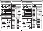
H3C EWP-WA6630X-JP-FIT, Installation Manual
The H3C EWP-WA6630X-JP-FIT is a cutting-edge wireless access point designed to provide seamless connectivity. Ensure a smooth installation by downloading the free and comprehensive Installation Manual from our website. This user manual covers step-by-step instructions and troubleshooting guides, helping you make the most of your device. [Website] is your go-to source for hassle-free downloads.
Share
Download


Reviews:
No comments
Related manuals for EWP-WA6630X-JP-FIT

Monitouch V9 Series
Brand: Hakko Electronics Pages: 16

EliteConnect SMC2555W-AG2
Brand: SMC Networks Pages: 2

WR404
Brand: Abocom Pages: 3

WGA15731
Brand: Watchguard Pages: 28

Hub D50 Home
Brand: Xunison Pages: 12

F5D8231-4ei
Brand: Belkin Pages: 104

TEW-815DAP
Brand: TRENDnet Pages: 58

AP 55C
Brand: Sophos Pages: 4

EA9350 v2
Brand: Linksys Pages: 19
Aterm W300P
Brand: NEC Pages: 4

PA-MR10LN
Brand: NEC Pages: 25

Aterm MR03LN
Brand: NEC Pages: 25
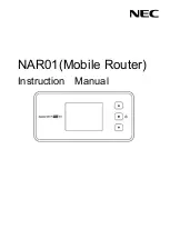
NAR01
Brand: NEC Pages: 26

UNIVERGE WL
Brand: NEC Pages: 34

OPS-DRD
Brand: NEC Pages: 46

NP06LM
Brand: NEC Pages: 48

B6R-W2
Brand: Well Straler Pages: 16

ALL02800N
Brand: Allnet Pages: 83


