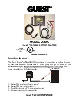
Chemistry Selection in Doubler Mode
27V Output
28V Output
25V Output
30A
50A
BROWN
Floating/No Connection
WHITE
GREEN
BLACK
RED
ORANGE
24V
LOAD
To Ignition Switch of vehicle
BLUE
Page 1 of 2
Model:
VDBC1224-20-NG-2
Next Generation DC to DC
Booster Battery Charger / Doubler
12VDC to 24VDC 20A
Operating Instructions
Please read these instructions before use
The VDBC1224-20-NG-2 joins our new NG series of units that uses the next
generation topology reducing the size and increasing the output power
compared to its previous VI and BC series of units.
In an extremely compact package (373cm³) the VDBC1224-20-NG-2
combines thefeatures of a doubler and a battery charger in a weather,
dust and vibration resistant package.
Features include:
• Dual Option - 3-Stage 24V Battery Charger or Voltage Doubler
• Peak Output : 20A
• Selectable output voltages for Lithium (29.6V/27.6V), Sealed Lead
Acid (28.4V/27V), Vented Lead Acid (29.2V / 27V) or Doubler (25V/27V/28V)
• Over Current and Temperature protections for extra product reliability.
• High Efficiency : Typical >95%
• Precise under voltage protection : No need for external isolator.
• Latched overload protection for preventing dangerously charging faulty batteries
• Remote LED indication for battery charge status.
• Very low standby current: <3mA
1.
Disconnect the battery supply.
2.
The following connection sequence is to be followed: Ground (BLACK), Output (BROWN), Input (RED), LED (GREEN),
Chemistry/Output Selection (Orange), ON/OFF (Blue) and Mode Select (WHITE). The BLACK and BROWN wires are to be connected as
directly as possible to the 12V input battery.
3.
The unit is protected from weather and dust but do not pressure wash or mount to areas that will be submerged. Avoid locations such
as fuel lines or where external heat is produced e.g. exhaust system or where the batteries are located.
4.
Chose a position with good ventilation where air can pass freely around the unit.
5.
Ensure the unit is protected from sources of contamination e.g. oil, grease and dust.
6.
Ensure that the unit is installed away from any flammable fumes, liquids or materials.
VDBC1224-20-NG-2
Note:
Before installation the user shall determine the suitability of the product to ensure correct application.
Wiring Diagram - For Doubler Setup
LED
Caution:
For all Floating or wires that are not used - Please isolate
or tape up wires to avoid accidental connection.
More information https://www.caravansplus.com.au