background image

Wood Lathe

ModeL G1067Z

InStructIon ManuaL

Copyright © 1996 By grizzly industrial, inC. revised July, 2009 (tr)

WarnInG: no portIon of thIS ManuaL May be reproduced In any Shape

 or forM WIthout the WrItten approvaL of GrIZZLy InduStrIaL, Inc.

 #5983 printed in taiwan.

Summary of Contents for G1067Z

Page 1: ...truction Manual Copyright 1996 By Grizzly Industrial Inc Revised July 2009 tr Warning No portion of this manual may be reproduced in any shape or form without the written approval of Grizzly Industrial inc 5983 printed in taiwan ...

Page 2: ...als are Lead from lead based paints Crystalline silica from bricks cement and other masonry products Arsenic and chromium from chemically treated lumber Your risk from these exposures varies depending on how often you do this type of work To reduce your exposure to these chemicals work in a well ventilated area and work with approved safety equipment such as those dust masks that are specially des...

Page 3: ...SSEMBLY 10 Pre assembly 10 Stand 10 Installing the Switch 11 Tool Rest 12 Tailstock 12 Spur Center 13 Face Plate 13 SECTION 3 ADJUSTMENTS 14 Headstock 14 Tailstock 15 Live Center 16 Speed Selector 16 SECTION 4 OPERATIONS 17 Test Run 17 Tool Rest 17 Spindle Turning 18 Outboard Turning 19 Indexing 19 SECTION 5 MAINTENANCE 20 General 20 Bed 20 Lubrication 20 SECTION 6 CLOSURE 21 Machine Data Sheet 22...

Page 4: ...lighted Indicates an imminently hazardous situation which if not avoided WILL result in death or serious injury Indicates a potentially hazardous situation which if not avoided COULD result in death or serious injury Indicates a potentially hazardous situation which if not avoided MAY result in minor or moderate injury It may also be used to alert against unsafe practices This symbol is used to al...

Page 5: ...o Safety Instructions For Power Tools 15 USE RECOMMENDED ACCESSORIES Consult the owner s manual for recom mended accessories The use of improper accessories may cause risk of injury 16 REDUCE THE RISK OF UNINTENTION AL STARTING On machines with magnet ic contact starting switches there is a risk of starting if the machine is bumped or jarred Always disconnect from power source before adjusting or ...

Page 6: ...re turning lathe on 6 SELECT THE TURNING SPEED which is appropriate for the type of work Allow the lathe to gain its full speed before using 7 ALWAYS INSPECT THE CONDITION of the materials you are turning Do not turn pieces with knots splits and other potential ly dangerous conditions 8 KEEP LATHE TOOLS PROPERLY SHARPENED and hold firmly in the proper position when turning 9 NEVER OPERATE THE LATH...

Page 7: ... have any service questions or parts requests please call or write us at the location listed below Grizzly Industrial Inc 1203 Lycoming Mall Circle Muncy PA 17756 Phone 570 546 9663 Fax 800 438 5901 E Mail techsupport grizzly com Web Site http www grizzly com The specifications drawings and photographs illustrated in this manual represent the Model G1067Z as supplied when the manual was pre pared ...

Page 8: ...f expedi ency replacements can be obtained at your local hardware store The Model G1067Z Wood Lathe is shipped from the manufacturer in a carefully packed carton If you discover the machine is damaged after you ve signed for delivery please call Customer Service immediately for advice Save the containers and all packing materials for possible inspection by the carrier or its agent Otherwise filing...

Page 9: ...e using solvents Lack of ventilation while using solvents could cause serious personal health risks fire or environmental hazards Always work in a well ventilated area to pre vent the accumulation of dangerous fumes Supply the work area with a constant source of fresh air Clean Up Unsupervised children and visitors inside your shop could receive seri ous personal injury Ensure child and visitor sa...

Page 10: ...gher are not adequate to protect the cir cuit Recommended Circuit Breaker 15 Amp Your Circuit Capacity Always check to see if the wires in your circuit are capable of handling the amperage load from your machine If you are unsure consult a qualified electrician If you operate this machine on any circuit that is already close to its capacity it might blow a fuse or trip a circuit breaker However if...

Page 11: ...ords This machine must have a ground prong in the plug to help ensure that it is grounded DO NOT remove ground prong from plug to fit into a two pronged outlet If the plug will not fit the outlet have the proper outlet installed by a qualified electrician Electrocution or a fire can result if the machine is not grounded correct ly Make sure all electri cal circuits are ground ed Do not use the mac...

Page 12: ... an end panel to any two of the legs using the 10 24 x 3 8 Phillips head screws provided Figure 1 Repeat this step for the remaining end panel legs DO NOT final tighten the bolts at this time Stand Pre assembly SECTION 2 ASSEMBLY Wear safety glasses dur ing the entire set up process This machine presents serious injury hazards to untrained users Read through this entire man ual to become familiar ...

Page 13: ...th the lathe set in place where it will be used 3 Attach the long stand supports to each end assembly using the 5 16 18 x 3 4 carriage bolts provided Figure 3 1 Locate the paddle switch 2 Press the paddle switch into the cut out on the face of the leg as shown in Figure 5 Do not plug cord in until you are ready to test run the lathe See Test Run section for instructions before initial run Installi...

Page 14: ...he bottom of the tool rest assembly 2 Set the tool rest assembly on the lathe bed with the clamp stud between the bed slot 3 Set the tool rest lock handle so it is pointing down Re install the lock plate and thread the hex nut back onto the stud until it bot toms out 4 Lift the lock handle approximately 90 and tighten the hex nut 1 2 to 2 3 of a turn more 5 Turn the tool rest lock handle until it ...

Page 15: ... the face plate using the mounting holes bored into the face plate To remove insert the knockout bar provided into the outboard spindle and tap with the palm of your hand while carefully holding onto the spur center with your other hand Figure 11 Knockout bar Face Plate Spur Center The joints of glued up workpieces should be high quality to prevent them from break ing under the extreme forces of l...

Page 16: ...ever Figure 14 Note The large hex nut under the headstock will require occasional adjust ing to assure proper clamping pressure to the bed Turn the hex nut in small increments to fine tune the clamping pressure 1 Loosen the quick release lever by pushing it down 2 Pull the spring loaded quick release set pin Figure 15 and rotate the headstock clock wise 90 or 180 Figure 13 Figure 14 Figure 15 Quic...

Page 17: ...tion the tailstock along the bed 1 Loosen the quick release lever and move the tailstock to the desired position Figure 18 2 Re engage the quick release lever 3 If the quick release lever will not lock the tail stock down onto the bed either too loose or too tight loosen or tighten the hex nut located on the underside of the tailstock in small increments as needed to achieve the proper clamping pr...

Page 18: ... stock housing about 1 2 Insert the live cen ter back into the tailstock barrel Speed Selector The variable speed selector has six position set tings These settings provide speeds of 500 800 1200 1600 2000 and 2700 RPM for varied appli cations To change speeds 1 Turn the lathe on 2 Pull the speed selector lever straight back away from the machine so the detent spring compresses Figure 20 3 Slowly ...

Page 19: ...while it is running Wait until the machine is turned off unplugged and all working parts have come to a rest before you do anything Serious personal injury may occur Once the assembly is complete and the adjust ments are done to your satisfaction you are ready to test the machine Turn on the power supply at the main panel Press the START button Make sure that your finger is poised on the STOP but ...

Page 20: ...ur 3 Hold the spindle vertically and support it on a solid surface Line up the spur center with the center of the workpiece Drive the spur center into the stock about 1 4 using a dead blow hammer Be careful not to split the workpiece See Figure 23 Wood with splits along the grain may fly off during the opera tion Note With dense wood drill a hole at the center and score lines with a saw blade for ...

Page 21: ... 90 The headstock spindle indexes every 15 by inserting the indexing pin into one of the holes in the headstock Indexing is desirable when locking the workpiece in position such as when routing flutes The spindle is drilled every 30 and the headstock housing has two holes that are drilled 15 apart To index the spindle 1 Insert the pin through the hole in the hous ing 2 Rotate the spindle by hand u...

Page 22: ...an be expected to last much longer All bearings are common sizes and can be easily obtained The bed and other non painted surfaces on the Model G1067Z should be protected against rust and pitting Wiping the lathe clean after every use ensures that moisture from wood dust isn t allowed to trap moisture against bare metal sur faces Make a habit of inspecting your lathe each time you use it Check for...

Page 23: ...ost safety measures are generally universal Grizzly reminds you that each work shop is different and safety rules should be con sidered as they apply to your specific situation We recommend you keep a copy of our current catalog for complete information regarding Grizzly s warranty and return policy If you need additional technical information relating to this machine or if you need general assist...

Page 24: ...1 x 12 TPI RH Bore Through Spindle 0 406 Tailstock Taper MT 2 Spindle Taper MT 2 Spur Center Number Range of Speeds 6 500 to 2700 RPM Motor Type TEFC Capacitor Start Induction Horsepower 1 2 HP Phase Cycle Single Phase 60 Hz Voltage 110V Amps 8 RPM 1720 Bearings Shielded Lubricated For Life Ball Bearings Switch Safety Key Toggle Switch Standard Features Swivel Head 6 Face Plate Articulated Tool Re...

Page 25: ...105V2 G1067Z Wood Lathe 23 ...
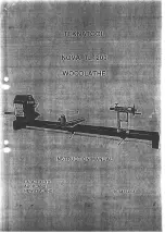
Page 26: ...59 59 46A 24 G1067Z Wood Lathe ...

Page 27: ...REAR 50 P1495050 TOOL REST body 51 P1067Z051 CROSS BRACE LONG ref part description 52 P1495051 ECCENTRIC ROD W 052 53 PB31 HEX BOLT 1 4 20 x 1 54 P1067Z054 TOOL REST W 070 55 P1495031 LOCKING LEVER 58 PN02 HEX NUT 5 16 18 59 pw07 flat washer 5 16 60 PCB01 CARRIAGE BOLT 5 16 18 x 5 8 61 P1067Z061 END PANEL 62 P1067Z062 CROSS BRACE SHORT 63 PS06 PHLP HD SCR 10 24 x 3 8 64 P1067Z064 MOTOR 1 2 HP 64 1...

Page 28: ... the State of Washington County of Whatcom We shall in no event be liable for death injuries to persons or property or for incidental contingent spe cial or consequential damages arising from the use of our products To take advantage of this warranty contact us by mail or phone and give us all the details We will then issue you a Return Number which must be clearly posted on the outside as well as...

Page 29: ...2 Which of the following magazines do you subscribe to ___American Woodworker ___Practical Homeowner ___Cabinetmaker ___Shop Notes ___Family Handyman ___Today s Homeowner ___Fine Homebuilding ___WOOD ___Fine Woodworking ___Wooden Boat ___Home Handyman ___Woodshop News ___Journal of Light Construction ___Woodsmith ___Old House Journal ___Woodwork ___Popular Mechanics ___Woodworker ___Popular Scienc...

Page 30: ...INDUSTRIAL INC P O BOX 2069 BELLINGHAM WA 98227 2069 Place Stamp Here TAPE ALONG EDGES PLEASE DO NOT STAPLE Name_______________________________ Street_______________________________ City______________State______Zip______ Send a Grizzly Catalog to a friend ...

Page 31: ...zly Trusted Proven and a Great Value OR SECURE ORDERING ORDERS SHIPPED WITHIN 24 HOURS E MAIL RESPONSE WITHIN ONE HOUR Visit Our Website Today And Discover Why Grizzly Is The Industry Leader Call Today For A FREE Full Color Catalog ...

Reviews: