background image

Shuttle

®

Brewer & Airpot/Shuttle

®

Brewers

Operation and Instruction Manual

For Models PB-330, PB-430, PBVSA-330, PBVSA-430, PBIC-330, PBIC-430, 

PB330E 230V, PB-430E 230V, PBVSA-330E 230V, 

PBVSA-430E 230V, PBIC-330E 230V, PBIC-430E 230V

Table of Contents

Warning Labels . . . . . . . . . . . . . . . . . . . . . . . . . . 3

Installation and Start-up  . . . . . . . . . . . . . . . . . . . 4

Operation  . . . . . . . . . . . . . . . . . . . . . . . . . . . . . . 6

Adjustments  . . . . . . . . . . . . . . . . . . . . . . . . . . . . 7

Programming  . . . . . . . . . . . . . . . . . . . . . . . . . . . 9

Cleaning  . . . . . . . . . . . . . . . . . . . . . . . . . . . . . . 13

Service  . . . . . . . . . . . . . . . . . . . . . . . . . . . . . . 14

Precision Brew® Control Board   . . . . . . . . . . . .15

Troubleshooting

Error Messages  . . . . . . . . . . . . . . . . . . . . . 17

Filling Problems  . . . . . . . . . . . . . . . . . . . . . 17

Heating Problems  . . . . . . . . . . . . . . . . . . . . 19

Brewing Problems . . . . . . . . . . . . . . . . . . . . 21

Parts List  . . . . . . . . . . . . . . . . . . . . . . . . . . . . . 24

Parts Photos  . . . . . . . . . . . . . . . . . . . . . . . . . . . 25

VS-1.5(S) Cleaning and Sanitizing  . . . . . . . . . .29 

Wiring Diagrams . . . . . . . . . . . . . . . . . . . . . . . . 30

© Grindmaster Corporation, 2004
PRINTED IN U.S.A.

Grindmaster Corporation

4003 Collins Lane
Louisville, KY 40245 USA
(502) 425-4776    
(800) 695-4500 (USA & Canada only)
(800) 568-5715 (Technical Service Only)
FAX (502) 425-4664
www.grindmaster.com

0607 Form # AM-344-04

Part # A090-840 

Prior authorization must be obtained from
Grindmaster Corporation for all warranty claims.

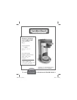
Models PB-330/PB-330E 230V

Models PBIC-430/

PBIC-430E230V

Models PBVSA-430/

PBVSA-430E 230V

Summary of Contents for AM-344-04

Page 1: ...or Messages 17 Filling Problems 17 Heating Problems 19 Brewing Problems 21 Parts List 24 Parts Photos 25 VS 1 5 S Cleaning and Sanitizing 29 Wiring Diagrams 30 Grindmaster Corporation 2004 PRINTED IN U S A Grindmaster Corporation 4003 Collins Lane Louisville KY 40245 USA 502 425 4776 800 695 4500 USA Canada only 800 568 5715 Technical Service Only FAX 502 425 4664 www grindmaster com 0607 Form AM ...

Page 2: ......

Page 3: ...sh panel and lid of machine Located on PB 330 PB 330E 230V PB 430 and PB 430E 230V lower front decal Order part A546 434 for PB 330 Order part A546 435 for PB 430 Part A546 213 Located on front splash panel Part A71949 Located on brew baskets Shuttle Brewers Airpot Shuttle Brewers Page 3 CAUTION Remove with care Hot liquid in brew basket could cause burns Located on PBIC 330 PBIC 330E 230V PBIC 43...

Page 4: ...tric and water hook up locations are behind the front panel Remove the four screws fastening this panel for access to these connections Water Hook up 1 The water line may enter through holes on the rear or the bottom of the brewer Use the right hand opening for water 2 Use 3 8 copper or flexible water line to prevent strain Do not use low temperature plastic tubing The connection to the fill valve...

Page 5: ...ly copper conductors 4 Standard connection is 1 phase 3 wire Connect the two lines to L1 and L2 on the terminal block If the brewer is wired for three phase a lug L3 is provided on the terminal block A neutral line must be connected to the N terminal Note PB xxxE 230V models are 1 phase 2 wire or 3 phase 3 wire and do not require a neutral 5 The body of the brewer must be grounded A ground lug is ...

Page 6: ...the filter basket Follow corporate recommendations for amount of coffee and grind A full Shuttle is 1 5 gallons 5 7L A full vacuum Shuttle is 1 6 6 0L gallons 5 Slide the basket into the brewer making sure the spout lines up with the top of the Shuttle 6 If ready lights are lit press correct batch size button 7 Brew spray time is about 4 minutes for a full Shuttle After the brew allow the coffee t...

Page 7: ...lses pulse on time and pulse off time for each size brew cycle can be set During the pulse off cycle water shuts off to the coffee grounds During this period the grounds in the brew basket absorb water causing the coffee bed to rise With a larger bed of coffee in the brew basket remaining water from spray head has more contact area with grounds causing greater extraction of finished coffee Note Ad...

Page 8: ...Valve closes Pulse 1 14 0 35 Brew Valve opens 15 0 55 Brew Valve closes Pulse 2 16 1 10 Brew Valve opens 17 1 30 Brew Valve closes Pulse 3 18 1 45 Brew Valve opens 19 4 45 Brew Valve closes 10 6 15 Ready Light stops flashing Pulse Brewing OFF Bypass ON Assumptions br 4 00 P b OFF rto 0 45 b P 20 max 31 Software calculates Brew valve on time 192 sec and Bypass Valve on time 107 sec 11 Press Brew bu...

Page 9: ...up or down arrow to change value increments of 1 19 Press Large Brew button to accept and go to next setting Note If OFF is selected skip pulse timing steps to 26 20 Display will read 0 05 0 60 pulse ON time for each pulse Default is 0 40 21 Press up or down arrow to change value increments of one second 22 Press Large Brew button to accept and go to next setting 23 Display will read 0 05 0 60 pul...

Page 10: ...of seconds shown PULSE ON TIME 0 05 0 60 of seconds shown OFF 1 6 OF PULSES OR OR TANK TEMP 170 205F PULSE OFF TIME 0 05 0 60 4 minutes 10 seconds shown PULSE BREW BREW TIME READING TEMP SCALE DISPLAY BREW TIME 0 01 6 00 0 45 for Standard Spray Head 0 64 for Gourmet Spray Head 1 PRESS AND HOLD UP DOWN ARROWS FOR 5 SECONDS 2 READY LIGHTS WILL FLASH 3 PRESS BREW BUTTON FOR LARGE L 4 LARGE READY LIGH...

Page 11: ...pulse timing steps 14 Display will read 0 05 0 60 pulse ON time for each pulse Default is 0 30 15 Press up or down arrow to change value increments of 1 second 16 Press Medium Brew button to accept and go to next setting 17 Display will read 0 05 0 60 pulse OFF time for each pulse Default is 0 30 18 Press up or down arrow to change value increments of 1 second 19 Press Medium Brew button to accept...

Page 12: ...mall Brew button to accept and go to next setting Note If Off is selected skip pulse timing steps 14 Display will read 0 05 0 60 pulse ON time for each pulse Default is 0 20 15 Press up or down arrow to change value increments of 1 second 16 Press Small Brew button to accept and go to next setting 17 Display will read 0 05 0 60 pulse OFF time for each pulse Default is 0 20 18 Press up or down arro...

Page 13: ...s with one gallon 2 3 full of hot water 12 Pour into the Shuttle liners the recommended concentration of urn cleaner excessive amounts of cleaner will attack the stainless steel Urn cleaners that have been used successfully DIP IT TABZ Super Concentrate manufactured by Reckitt Benckiser Inc manufactured by Urnex Brands Inc 1655 Valley Road 170 Ludlow Street Wayne NJ 07474 Yonkers NY 10705 800 228 ...

Page 14: ...Brewer may contain over 5 gallons 19 0L of hot water 1 Prepare a heat resistant container to drain tank water into 2 Disconnect power to the brewer 3 Remove the front access panel 4 Pinch or clamp the silicone hose connected to fill valve 5 Disconnect hose from outlet barb on fill valve 6 Place hose over drain and release clamp 7 Allow the tank to drain completely NOTE It may be necessary to pinch...

Page 15: ... will scroll donE to show completion of a system restore Upon a successful restore the original factory settings will override all changes The brew counters are not affected Factory Specific Features The following sections describe features that are not intended to be used by the end user These features instead are intended to help Grindmaster set up and test the machine Factory Field Test Menu Th...

Page 16: ...eater level If 500 water level not at the heater level 9 Show Input Display scrolls InPut Input Test Mode 10 Input Test Press each key and the display will show a number related to that key Right Side On Off 1 advances test Up 5 Down 3 Large Brew 4 Medium Brew 2 Small Brew 0 Basket Switch 17 Left Side On Off 9 Up 13 Down 11 Large Brew 12 Medium Brew 10 Small Brew 8 Basket Switch 16 11 Show Output ...

Page 17: ...ctions and reset controller If error reoccurs replace thermistor ER3 Thermistor is reading out of range Check tank temperature Replace thermistor ER4 No heat is detected See Heating Problems See Heating Problems Filling Problems Problem Possible Causes Service Check Remedy Overfilling water tank when power is Off Fill valve not sealing properly Check to see if water enters tank continuously usuall...

Page 18: ...onnecting terminals See wiring diagram for more information Ensure there is proper voltage across terminal block Check wiring diagram for more information Disconnect quick disconnect on secondary side of transformer at quick disconnect between yellow and blue wires Check for 24 Vac between blue and yellow wires Establish electrical power to unit Establish water supply to unit If there is not 120V ...

Page 19: ...re and there is 24 Vac across fill valve terminals replace fill valve Heating Problems Problem Possible Causes Service Check Remedy Tank does not heat No electrical power to equipment No power to control board Check for proper voltage at terminal block Check circuit breaker on supply circuit Check for proper voltage across transformer primary terminals by disconnecting terminals See wiring diagram...

Page 20: ...to ensure connections from relay to thermal cut out and from thermal cut out to contactor and from contactor to proper ter minal of terminal block are secure See wiring diagram for more info mation Ensure that coil on heater relay is energized by ensuring that there is 24 VDC between the gray and blue wires attached to the relay Remove the black and brown wires from the relay and check for an open...

Page 21: ...tions between N terminal of contactor coil and terminal block If the contactor coil is energized and there is an open circuit across any of the contactor poles replace contactor If resistance is much less than 8 Ohms or much more than 15 Ohms replace heater s If 5 pin connector is securely attached to control board and all connections are secure and functioning except there is not 120 Vac across c...

Page 22: ...ces operating Plumb water supply so that water pressure is not significantly affected by other appliances Brew cycle will not start Optional momentary switch to indicate container in place not engaged or faulty Brew circuit connections not secure Brew valve faulty Touchpad faulty Check to see that container fully engages switch Check for continuity across switch when switch is engaged Check to see...

Page 23: ...ol board Sprayhead will not stop dripping water Brew valve not closing completely Water in tank boiling Visually inspect brew valve at hose connections Remove sprayhead and determine if drip is coming from overflow Clean lime from valve Seat cup or entire valve may need replacement Reduce tank temperature If you still need help call our Service Department at 800 695 4500 USA and Canada only or 502...

Page 24: ...ontactor for 4 Pole E230V models E531 076 32 Transformer 120 208 240 100W A554 137 33 Valve Brew 24VAC PB A537 184 34 Valve Bypass 24VAC PB A537 183 35 Solenoid Basket Lock 24vdc A554 135 36 Touchpad PB Series A530 057 prior to May 2007 A530 060 after May 2007 37 Board AC DC Rectifier A530 058 prior to May 2007 only 38 Spray Elbow A518 046 39 Tee Barbed 3 8 A61152 40 Hose Overflow A585 016 41 Hose...

Page 25: ... Brewers Airpot Shuttle Brewers Page 25 Front View refer to key on page 24 2 1 7 3 4 6 Lower Warmer refer to key on page 24 PB 430 pictured 23 23 22 21 20 21 22 5 prior to May 2007 6 5 1 7 3 4 2 after May 2007 ...

Page 26: ...Page 26 Shuttle Brewers Airpot Shuttle Brewers Top View refer to key on page 24 42 30 34 Tank Lid refer to key on page 24 3 Heater Model shown 50 52 51 50 36 35 38 35 32 36 ...

Page 27: ... Clip A548 142 6 Lid Stopper w O Ring A548 140 A61365 S S Cover used until August 2001 5 6 4 3 2 1 Shuttle Parts List for PB 330 and PB 430 only A537 055 Handle A522132 Bonnet Nut A522120 Spring A537 047 Plastic Stem A522102 Silicone Seat Cup Upper Faucet Part A537 049 Gauge Assembly Part A718 018 A318 119P Top Gage Fitting A522026 Washer Upper Gage A555 001 Gage Shield A522031 Gage Glass A522027 ...

Page 28: ... Tray Top A517 018 1 6 Self Tapping Screw 5 A539 217 4 7 Rubber Foot A548 161 4 8 Plastic Insert A548 162 3 9 Self Tapping Scres 75 A539 218 3 ITEM NO Title PART NUMBER VS S QTY 1 Stand Body A548 157 1 2 Tray for Stand A548 159 1 3 Stand Base A548 158 1 4 Tray Top A517 018 1 5 Stand Top Plate A517 019 1 6 NUT M4 W Nylon Insert A540 237 4 7 Self Tapping Screw 5 A539 217 4 8 Rubber Foot A548 161 4 M...

Page 29: ...nitizing body assembly a Remove unit from the base only when using VS S with VS 1 5 b Completely fill the unit with cleaning solution Using a clean cloth wipe the unit thoroughly c Rinse unit thoroughly with fresh water d Remove faucet shank and sight gauge from unit and place in cleaning solution e Open lid on the bottom of the unit and remove silicon tube Tank to Faucet Tube and place in cleanin...

Page 30: ...Page 30 Shuttle Brewers Airpot Shuttle Brewers Wiring Diagram Precision Brew 430 Series Models PB 430 PBVSA 430 and PBIC 430 Prior to May 2007 ...

Page 31: ...Shuttle Brewers Airpot Shuttle Brewers Page 31 Wiring Diagram Precision Brew 330 Series Models PB 330 PBVSA 330 and PBIC 330 Prior to May 2007 ...

Page 32: ...Page 32 Shuttle Brewers Airpot Shuttle Brewers Wiring Diagram PB 430E 230V PBVSA 430E230V PBIC 430E 230V Single or Three Phase Models Prior to May 2007 ...

Page 33: ...Shuttle Brewers Airpot Shuttle Brewers Page 33 Wiring Diagram PB 330E 230V PBVSA 330E 230V PBIC 330E 230V Brewers Prior to May 2007 ...

Page 34: ...Page 34 Shuttle Brewers Airpot Shuttle Brewers Wiring Diagram Precision Brew 430 Series Models PB 430 PBVSA 430 and PBIC 430 After May 2007 ...

Page 35: ...Shuttle Brewers Airpot Shuttle Brewers Page 35 Wiring Diagram Precision Brew 330 Series Models PB 330 PBVSA 330 and PBIC 330 After May 2007 ...

Page 36: ...Page 36 Shuttle Brewers Airpot Shuttle Brewers Wiring Diagram PB 430E 230V PBVSA 430E230V PBIC 430E 230V Single or Three Phase Models After May 2007 ...

Page 37: ...Shuttle Brewers Airpot Shuttle Brewers Page 37 Wiring Diagram PB 330E 230V PBVSA 330E 230V PBIC 330E 230V Brewers After May 2007 ...

Page 38: ...Page 38 Shuttle Brewers Airpot Shuttle Brewers Wiring Diagram Heater Configuration 3 Heater ...

Page 39: ...Shuttle Brewers Airpot Shuttle Brewers Page 39 Wiring Diagram Heater Configuration 1 Heater ...

Page 40: ...erage Dispensers Crathco Cold and Frozen Beverage Dispensers AMW Coffee and Tea Systems Tel 502 425 4776 Fax 502 425 4664 1 800 695 4500 USA Canada only P O Box 35020 Louisville KY 40232 USA www grindmaster com email info grindmaster com Grindmaster Corporation 2003 PRINTED IN USA 0607 Form AM 344 04 Part A090 840 ...

Reviews: