background image

Checking the Outer Casing

Checking the Accessories

Setting and Checking the AC Line Frequency

After unpacking, check the GL820's Exterior to make sure that 

there are crack or other damage before use.

Set the AC line frequency in the “OTHR” menu. This setting 

(50 or 60 Hz) affects the noise reduction performance of the device.

o Quick Start Guide : 1

o CD-ROM : 1

o AC cable/AC adapter : 1

Don't forget to

check the setting

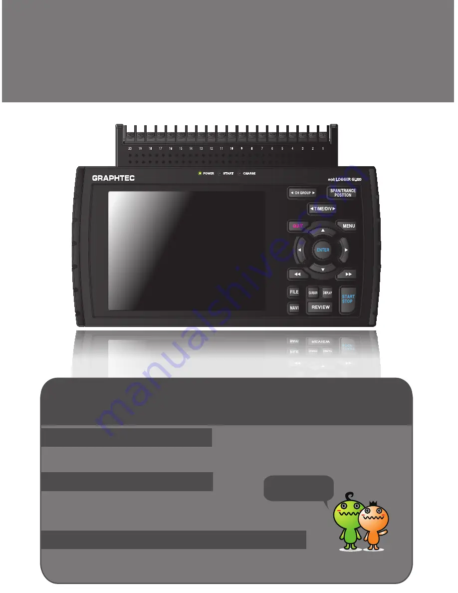
Thank you for choose the midi LOGGER GL820.

This Quick Start Guide describes the basic operations.

Please refer to the manual (PDF) in the CD-ROM for more information.

Quick Start Guide

GL820

midi LOGGER

GL820-UM-851

Summary of Contents for GL820

Page 1: ...ine frequency in the OTHR menu This setting 50 or 60 Hz affects the noise reduction performance of the device o Quick Start Guide 1 o CD ROM 1 o AC cable AC adapter 1 Don t forget to check the setting Thank you for choose the midi LOGGER GL820 This Quick Start Guide describes the basic operations Please refer to the manual PDF in the CD ROM for more information Quick Start Guide GL820 midi LOGGER ...

Page 2: ...red for Data Capture 2 Setup How to Make the Settings 3 Data Capture How to Capture Data 4 Data Replay How to Replay Captured Data Convenient Functions Trigger Functions to Control Data Capture Start Stop Operations Span Position and Trace Functions to Adjust the Waveform Display Specifications Standard Specifications External Input Output Functions Input Unit Specifications Installation Guide 1 2...

Page 3: ...atus LED POWER START CHARGE Battery cover Label GND terminal AC adapter jack External input output terminals LOGIC PULSE EXT TRIG SAMPLE ALARM Power switch GL820 Nomenclature Top Panel Bottom Panel Front Panel 2 Humidity sensor is the option B 530 Logic alarm cable is required for connection Cable is the option B 513 Two battery pack can be installed Battery pack is the option B517 ...

Page 4: ...above the GND terminal while connecting the grounding cable to the GL820 Connect the other end of the cable to ground Note Connect wires to the specified channel the channel number is shown on top of the terminal block A B b b Voltage input CH1 CH20 Thermocouple input Lead wire resistance should be 10 Ω or less per wire three wires need to be same length Resistance temperature detector input Curre...

Page 5: ... according to noise type Ex 1 Connect the GL820 s GND to ground Ex 2 Connect GL820 s GND to measurement object s GND Ex 3 In the AMP settings menu set filter to any setting other than OFF Ex 4 Operate GL820 with batteries Option B 517 Ex 5 Set the sampling interval which enables GL820 s digital filter see table below Precautions to Observe When Performing Measurement 4 Number of Measuring Channels...

Page 6: ...Press the side to switch to the previous group Press the side to switch to the following group 5 2 SPAN POSI TRACE 1 CH GROUP 3 TIME DIV 4 MENU 5 QUIT 6 DIRECTION KEYS ENTER Password setting 7 ENTER 8 FAST FORWARD KEY LOCK 9 START STOP USB DRIVE MODE 10 REVIEW 11 DISPLAY 12 CURSOR ALARM CLEAR 13 FILE 14 NAVI MONITOR SPAN POSITION TRACE Displays digital values default Used to change span settings c...

Page 7: ...n mode in the file settings box Hold down both keys simultaneously for at least two seconds to enable key lock status To cancel key lock status press them again for at least two seconds The key lock status can be confirmed by the status of the key lock lamp on the monitor Note Pressing these keys simultaneously with the key ENTER key enables password protection for the key lock operation 6 AMP DAT...

Page 8: ...ions during the Free Running status and during data capture and data replay operations 9 START STOP USB DRIVE MODE Press the START STOP key to perform start and stop of a data capture while the GL820 is in the Free Running status If this key is held down while the power to the GL820 is turned on the GL820 goes into USB Drive Mode Note Refer to the User s Manual in the supplied CD ROM for more info...

Page 9: ...rm generated white alarm not generated 13 Pen display Displays the signal positions trigger positions and alarm ranges for each channel see right figure 14 File name display area Displays the data capture file name during the data capture operation When data is being replayed the display position and cursor information is displayed here 15 Scale lower limit Displays the lower limit of the scale of...

Page 10: ...ge measurement is performed here Purpose of data capture To measure the temperature of the target objects Temperature Range T Thermocouple Voltage range 1V Sampling interval 1 sec Data save destination Internal memory device Measurement object 1 Connect Thermocouple to the CH 1 terminal Temperature 2 Connect wire to the CH 2 terminal Voltage 3 Connect the AC power supply 4 Turn on the power supply...

Page 11: ...cedure described above select Off for CH 3 to CH 10 Use the CH GROUP key to switch to the CH11 to CH20 group Make the settings required for data capture Here we will make only those settings that are minimum requirement The other settings will be not changed from the factory default settings Basic Setup Menu Operation Examples of selection menu operations AMP screen The key the ENTER key and the Q...

Page 12: ... MEM item in the following screen press the ENTER key 3 The file settings box shown in the following screen opens This box is used to specify file names for the GL820 s internal memory and for the USB memory device 4 Move the cursor to MEM and then press the key Press the key to move the cursor to and then press the ENTER key 5 A text input box is displayed Let s create a folder named TEST Input T...

Page 13: ...When this setting has been completed data will be captured and saved to the TEST folder in the internal memory with an automatic file name 8 Available space in specified memory device and time for data capture are displayed in the lower part of the Record Settings menu The data capture time can be checked Minimum required setting for data capture is completed 12 ...

Page 14: ... capture is completed 3 Data Capture How to Capture Data All of setting for the data capture have been set capturing data can be started now During the data capture operation let s also replay some data that was captured previously elapsed time capturing message remaining time for data capture The indication becomes when the data capture time is 9999 hours or more 13 Data can be replayed while bei...

Page 15: ...he cursor Note Press the CURSOR key to switch between A and B cursors Move the cursor using the keys or the keys Desired level values and time can be checked by moving the cursor Press the QUIT key to end the data replay operation A confirmation message is displayed Press the ENTER key Data replay ends and the GL820 goes into the Free Running status 4 Data Replay How to Replay Captured Data When d...

Page 16: ...nd select Level 3 Move the cursor to the Mode parameter for the CH 1 and then select Hi The GL820 has various functions that enable it to be used more effectively The selected three functions are described with details in the following Trigger Functions to Control Data Capture Start Stop Operations GL820 Convenient Functions 15 For example The trigger function performs operations such as the follo...

Page 17: ... TRIG menu screen Press the QUIT key to return the GL820 to the Free Running status 8 Press the START STOP key to start data capture If the trigger condition has not been satisfied the GL820 goes into the Armed status as shown on the following screen When the trigger condition has been satisfied data capture starts and the Memory Recording is displayed Elapsed time for data capture appears Numeric...

Page 18: ...ng has been changed the waveform screen scale will be set to 80ºC to 20ºC 3 How to make a Trace setting The Trace parameter can be used to specify the selected waveform to be visible or invisible on the display 1 Press the SPAN POSITION TRACE key to select the TRACE mode 2 Use the and keys to make CH 1 active enlarged display 3 Use the and keys to select Off When this setting has been changed the ...

Page 19: ...5 to 24 VDC 26 4 V max Battery pack option 7 4 VDC 2200 mAh 17Wh two packs required Power consumption AC power consumption when using the AC adapter provided as a standard accessory No Condition Normal During recharging battery 1 When the LCD is on 18VA 32VA 2 When the screensaver is operating 14VA 30VA DC current consumption No Condition Normal During recharging battery 1 24V When the LCD is on 0...

Page 20: ...ype JPt100 Pt100 Pt1000 Temperature Humidity Voltage Photo MOS relay scanning system all channels isolated balanced input 10ms 1ch M3 screw type 20 channels maximum 200 channels with extension unit Thermocouple Resistance temperature detector 20m 50m 100m 200m 500m 1 2 5 10 20 50 1 5V F S Thermocouple K J E T R S B N W WRe5 26 Resistance temperature detector Pt100 JPt100 Pt1000 IEC751 0 to 100 vol...

Page 21: ...are stored on the supplied CD ROM Install the USB driver according to this manual The manual location D USB Driver English GL USB UM152 PDF Note D drive name of CD ROM The letter of CD ROM drive vary it with the CD ROM drive of your PC To Install GL820 Application Software To install the application software which sets and controls the GL820 follow the directions below 1 Insert the accompanying mi...

Page 22: ...Specifications are subject to change without notice GL820 Quick Start Guide GL820 UM 851 Publisher GRAPHTEC CORPORATION May 1 2010 1st edition 01 ...

Reviews: