


INSTRUCTIONS-PARTS LIST
307–758
Rev. R
Supersedes Rev. P
ELECTRIC, 120 VAC
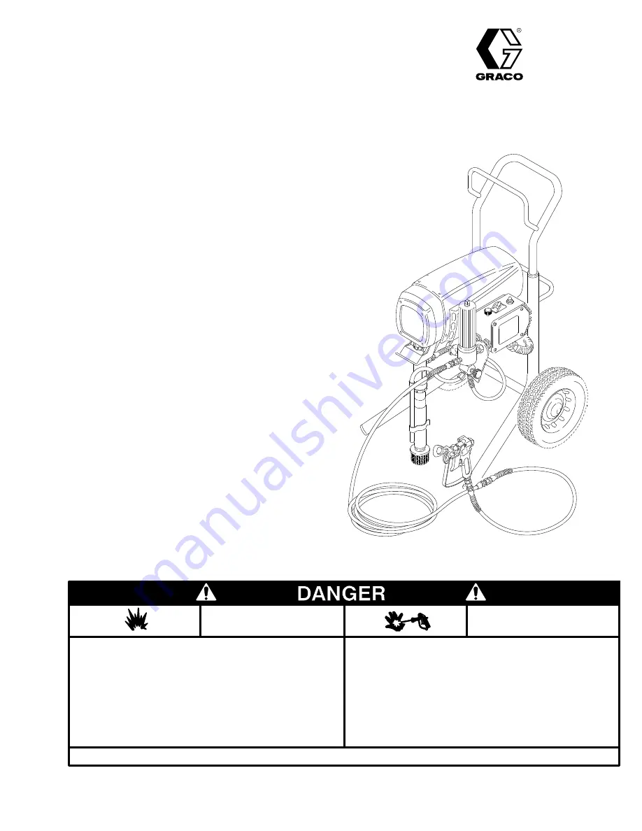
ULTRA
500 AIRLESS PAINT SPRAYER
2750 psi (195 bar) MAXIMUM WORKING PRESSURE
Model 231–032, Series C
Basic sprayer on Upright cart
Model 231–041, Series B
Complete sprayer on Upright cart, hoses, gun,
RAC IV
DripLess
Tip Guard and SwitchTip
Model 231–054, Series D
Basic sprayer on Lo-Boy cart without hose or gun
Model 231–055, Series B
Complete sprayer on Lo-Boy cart, hoses, gun,
RAC IV
DripLess
Tip Guard and SwitchTip
U.S. PATENT NO. 4,323,741, 4,397,610
PATENTED 1983, CANADA
AND OTHER PATENTS PENDING
GRACO INC.
P.O. BOX 1441
MINNEAPOLIS, MN
55440–1441
COPYRIGHT 1986, GRACO INC.
This manual contains IMPORTANT
INSTRUCTIONS and WARNINGS.
READ AND RETAIN FOR REFERENCE.
Liquids can be injected into the body by high pressure airless spray
or leaks – especially hose leaks.
Keep body clear of the nozzle. Never stop leaks with any part of the
body. Drain all pressure before removing parts.Avoid accidental trig-
gering of gun by always setting safety latch when not spraying.
Never spray without a tip guard.
In case of accidental skin injection, seek immediate
“Surgical Treatment”.
Failure to follow this warning can result in amputation or serious
injury.
FIRE AND
EXPLOSION HAZARD
SKIN INJECTION
HAZARD
READ AND UNDERSTAND ALL LABELS AND INSTRUCTION MANUALS BEFORE USE
Spray painting, flushing or cleaning equipment with flammable liq-
uids in confined areas can result in fire or explosion.
Use outdoors or in extremely well ventilated areas. Ground equip-
ment, hoses, containers and objects being sprayed.
Avoid all ignition sources such as static electricity from plastic drop
cloths, open flames such as pilot lights, hot objects such as ciga-
rettes, arcs from connecting or disconnecting power cords or turn-
ing light switches on and off.
Failure to follow this warning can result in death or serious injury.
NOTE: This is an example of the DANGER label on your sprayer.
This label is available in other languages, free of charge.
See page 46 to order.


