background image

- For Water-Based Materials Only -

(Consult your Material Supplier for Warnings and Application Requirements)
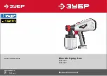
Model: 248650

Maximum Working Air Pressure:

 45 psi (3.1 bar)

Maximum Working Fluid Pressure:

 100 psi (6.9 bar)

Important Safety Instructions

Read all warnings and instructions in this manual. 
Save these instructions.

NOTICE

Use RTX 1500 non-bleeder texture gun (model 
248903) only. All other guns will damage sprayer.

ti4500b

310717E

Repair and Parts

TexFinish™ 1500 Rental Sprayer

Summary of Contents for TexFinish 1500 248650

Page 1: ...ir Pressure 45 psi 3 1 bar Maximum Working Fluid Pressure 100 psi 6 9 bar Important Safety Instructions Read all warnings and instructions in this manual Save these instructions NOTICE Use RTX 1500 non bleeder texture gun model 248903 only All other guns will damage sprayer ti4500b 310717E Repair and Parts TexFinish 1500 Rental Sprayer ...

Page 2: ...nguisher in the work area Equipment Misuse Hazard Equipment misuse can cause death or serious injury Do not exceed maximum working pressure or temperature rating of lowest rated system compo nent See Technical Data in all equipment manuals Use fluids and solvents that are compatible with equipment wetted parts See Technical Data in all equipment manuals Read fluid and solvent manufacturer s warnin...

Page 3: ...nch or amputate fingers and other body parts Keep clear of moving parts Do not operate equipment with protective guards or covers removed Pressurized equipment can start without warning Before checking moving or servicing equipment follow the Pressure Relief Procedure in this manual Disconnect power or air supply Personal Protective Equipment Wear appropriate protective equipment when operating se...

Page 4: ...Component Identification 4 310717E Component Identification 0 4 5 3 2 6 7 8 ti4500b ...

Page 5: ...Hopper D Hopper Connect Disconnect E Graco RotoFlex HD Pump F Material Outlet H Air Outlet K Fluid Flow Regulator and Pressure Gauge L Gun Nozzle 5 sizes M Gun see manual 310616 P Prime Switch R Power Cord S Pump Access Screw T Hose 25 ft U Material Thickness Gauge V Cleaning Ball W Spare Hose Gaskets X Hour Meter ...

Page 6: ...l current The sprayer cord includes a grounding wire with an appro priate grounding prong The plug must be plugged into an outlet that is properly installed and grounded in accordance with all local codes and ordinances Do not modify plug If it will not fit in outlet have grounded outlet installed by a qualified electrician Sprayer electric requirements are provided on page 6 Extension Cords Only ...

Page 7: ...tional hose sec tions can be added Total final length of hose used should not exceed 100 feet in length Hour Meter The TexFinish Sprayer is equipped with a SenDEC Hour Meter to monitor the number of hours the sprayer has been used After 40 hours the display will flash This flashing is your reminder to change the RotoFlex HD Pump hose After you have replaced the RotoFlex HD Pump hose reset the hour...

Page 8: ...cing Hopper 1 To replace hop per position drain over fitting as far as it will go making sure identification label faces out 2 Hand tighten fit ting Front Cover Removing Cover 1 Remove hopper 2 Unscrew and remove knob S 3 Place you hand under front bot tom edge of cover 3a Lift cover up 3b then pull bottom toward you and out to remove cover Replacing Cover 1 Place your hand under front bottom edge...

Page 9: ... remove 6 screws 2 on top and each side from cover 2 Lift cover up and then tilt it back and off sprayer frame Replacing Cover 1 To reposition cover on sprayer frame tip the cover back toward you and slide it down into place in the base of the frame Then push the top back into place Align screw holes in side and top of cover with holes in frame 2 Replace and tighten screws ti4430a ti4431a ti4432a ...

Page 10: ...nd remove knob 3 Slide RotoFlex HD hose off rollers 4 Rotate pump assem bly sideways Pull entire assembly out of front of sprayer frame 5 Separate the inner and outer hose brackets 6 Slide hose ends out of slots in outer hose bracket Slide out of short slot first 7 Pull hose out of inner hose bracket 8 Discard pump hose ti4377a ti4378a ti4374a ti4519a ti4376a ti4379a IMPORTANT After replacing Roto...

Page 11: ...first 5 Slide plates together inserting inner plate in outer plate matching alignment holes 6 Replace bracket assembly in housing making sure the mounting screw hole located in the top center of the inner plate faces up 7 Slide pump hose around rollers Make sure the rollers are horizontally parallel to each other 8 Slide feet on the bot tom of hose bracket into the slot on the bottom of sprayer No...

Page 12: ...urned all the way down 2 Pour approximately 1 gallon hot water in sprayer hopper to lubricate the pump 3 Turn power switch A on 4 Hold in prime switch P 5 Turn fluid flow regula tor K up to full pres sure 6 Run sprayer dry for 1 to 1 1 2 minutes ti4303a 7 4 2 ti4653a P ti4364a ti4655a ti4301a ...

Page 13: ... and back covers page 8 Remove hose extension and RotoFlex HD Pump assembly from frame page 10 1 Remove two screws and access cover on the left side of the motor 2 Remove ground nut and disconnect green ground wire 3 Disconnect black and white wires to motor 4 Loosen 4 bolts 2 each side to loosen tension on belt 5 Slide belt off motor pully 6 Disconnect air line from compressor to cooler and remov...

Page 14: ... 2 3 turns Do not remove them 9 Remove single shoulder bolt on other side of motor completely 10 Slide out motor assembly 11 Completely remove old shoulder bolts and rubber mounts 12 Thoroughly clean inside housing to remove dust and debris ti4463a ti4425a ti4462a ti4464a ...

Page 15: ...ce end cover Replace and tighten 3 screws 5 Reattach air line to cooler and compressor Tighten fitting 6 Slide belt over pulleys and set tension See Replacing Belt page 18 7 Reattach black and white wires to motor 8 Replace reattach green ground wire and ground ing nut 9 Replace cover plate and screws 10 Replace RotoFlex HD Pump and hose exten sion page 11 11 Replace front and back covers and hopp...

Page 16: ...n sprayer section page 8 Then remove back cover page 8 1 Disconnect air line to motor 2 Remove 3 screws in side of motor cover Remove cover 3 Remove fan bolt from center of fan and remove fan from housing 4 Remove 3 8 in bolt hold ing piston to motor shaft 5 Loosen 4 bolts on top of motor housing 6 Remove bolts and housing from motor 7 Remove piston rod from motor 8 Using parts in kit replace pist...

Page 17: ...piston bolt 3 Replace top motor hosing and 4 bolts 4 Tighten bolts 5 Replace motor fan and center fan bolt 6 Tighten bolt 7 Replace motor cover and screws 8 Reconnect air line from motor to cooler 9 Replace back cover See Removing and Replacing Hopper Front and Back Cover page 8 ti4700a ti4701a ti4703a ti4704a ti4485a ...

Page 18: ...support rod on one side of motor and ease it out of the holding bracket far enough to remove old belt Discard old belt At the same time slide in the new belt Replacing Belt 1 Using new belt from Kit position new belt around pulleys making sure the teeth in the belt are properly engaged with teeth on pul leys 2 Replace support rod Tighten 2 bolts 1 each side to secure supporting rod 3 Insert crow b...

Page 19: ...nd hose extension page 11 8 Replace back and front covers and hop per See Removing and Replacing Hopper Front and Back Cover page 8 A correctly tensioned belt will feel very tight To measure correct tension apply 4 5 lbs pressure at belt midpoint with thumb Belt should have approximately 1 8 in 3 175 mm deflection A loose belt will not last long If in doubt tighten more ti4477a ti4394a ti4473a ...

Page 20: ...hose extension and RotoFlex HD Pump assembly from frame page 10 1 Remove snap ring 2 Remove roller assem bly from rotor pins a 3 Clean rotor pins a and check for damage If pins are worn or dam aged replace rotor assembly Rotor Assembly Replace ment page 21 Reassembly 1 Replace roller assem bly 2 Reinstall snap ring 3 Replace RotoFlex HD Pump and hose exten sion page 11 4 Replace back and front cov...

Page 21: ...page 10 1 To prevent rotor assembly from moving insert a long screw driver or pry bar in the pulley 2 Remove large bolt and washer in center of rotor assembly 3 Pull rotor assembly off shaft Reassembly 1 Put new rotor assembly from kit on shaft 2 Insert a wrench in the pulley to prevent it from moving 3 Replace bolt Torque to 40 ft lbs 4 Replace RotoFlex HD Pump and hose exten sion page 11 5 Repla...

Page 22: ...r key located on the end of the cylin der pin by using a pliers to straighten the ends and pull it out of the hole 4 Gently push cylinder forward relieving tension on pin Pull out pin 5 Lift cylinder up and pull it back 6 Remove dampening grommet 7 Using a 15 16 in wrench loosen nut located inside sprayer frame at the end of the air cylinder 8 Using a 15 16 in wrench loosen nut on the other side o...

Page 23: ...dampening grommet 5 Align hole in end of air cyl inder and replace pin 6 Replace cotter pin through hole in pin bending ends to secure 7 Reattach electric wire terminals Terminals are not polarity sensitive and can be connected to either post 8 Gently push hose in quick release fitting 9 Replace RotoFlex HD Pump and hose exten sion page 11 10 Replace front cover and hopper See Removing and Replac ...

Page 24: ...ld 3 Disconnect wires to Relief Valve Pay attention to their location to ensure they are reattached correctly 4 Remove 2 nuts securing Relief Valve to sprayer 5 Remove Relief Valve from sprayer frame Reassembly 1 Position new Relief Valve from Kit in back of sprayer 2 Replace and tighten screws 3 Reattach wires to Relief Valve 4 Reattach air line from cooler to manifold 5 Reattach air line to regu...

Page 25: ...page 10 1 Disconnect all wire connections 2 Rotate coun ter clockwise to remove sensor from manifold Reassembly 1 Rotate new sensor from kit clockwise all the way into opening in Relief Valve housing Lightly tighten nut 2 Reconnect all wires 3 Replace RotoFlex HD Pump and hose extension page 10 4 Replace back and front covers and hopper See Removing and Replacing Hopper Front and Back Cover page 8...

Page 26: ...ents page 6 Breaker tripped Reset breaker Pump won t pump material or low output Air lock Open air valve on gun Mix too thick Add water to thin material Use Mate rial Thickness Gauge Loose fittings Check and retighten all fittings Plugged gun Relieve Pressure page 6 Remove gun from hose Clean gun RotoFlex HD Pump worn out Replace hose Pump cold or material frozen in pump Move pump to warm room and...

Page 27: ...crease flow control setting Plugged or dirty gun Relieve Pressure page 6 Clean gun Kinked hose Unkink hose Gun fluid flow adjustment set too low Increase flow adjustment with flow adjustment nut Intermittent flow sputtering or air in material Hopper connection not tight Check gasket Tighten connection Debris in system Clean Air quick disconnect does not stay connected Dirty or corroded fitting Cle...

Page 28: ...ram Wiring Diagram 82 16 47 17 54 58 Air Cylinder Guage Air Flow Control Air Cooler Air Compressor One Way Valve One Way Valve Regulator ti4369a REEN LACK 7HITE 3WITCH 0RIME 3WITCH IR YLINDER IR OMPRESSOR IR LOW ONTROL 0OWER ti4370c ...

Page 29: ...Parts 310717E 29 Parts 3 6 7 10 14 19 18 23 24 25 26 29 30 35 50 58 59 71 70 66 72 ti8084a 12 27 60 20 77 15 5A 5B 5 17 93 89 90 91 92 81 83 28 8 105 107 106 55 93 101 ti8084a ...

Page 30: ...CKET hose inner 1 27 287314 KIT RotoFlex HD Pump 1 28 189286 LABEL warning 1 29 118885 HOSE coupled includes grommet 1 30 287254 FRAME texture blue 1 32 15D633 WIRE jumper 1 35 116478 WHEEL pneumatic 2 39 15D628 CONDUCTOR ground 1 50 15D630 CORD power 1 51 15D634 WIRE jumper 1 54 116666 TUBE air 1 55 287304 HOSE SET twin line 1 in x 25 ft 1 58 116720 COUPLER air quick disconnect 1 59 104641 FITTIN...

Page 31: ...Parts Compressor 310717E 31 Parts Compressor 56 49 53 41 13 62 63 37 38A 38 1E 42 38B 4 36 45 73 1A 1C 88 88 63 62 57 52 1D 102 52 34 9 21 1B 31 9 43 33 22 40 19 49A 49B 49C 67 ...

Page 32: ...G retaining ext 2 38B 117726 WASHER nylon 4 40 103785 RIVET 2 41 287327 KIT repair shaft bracket pump assbly 1 42 287256 BRACKET compressor 1 43 118869 TUBE 1 45 15D610 SHAFT motor mount 1 49 287346 SHIELD rear assbly includes 19 49A 49B 49C 1 49A 15D561 COVER tool tray 1 49B 15D939 LABEL warning English French Spanish 49C 15D940 LABEL identification 52 116937 BEARING flanged bronze 2 53 117630 SC...

Page 33: ...US gallons 57 liters Maximum delivery with texture material 2 0 gpm 7 57 lpm Dimensions Length 27 in 685 8 mm with handles Width 26 in 660 4 mm Height 40 in 1016 mm Weight With hoses and gun 147 lb 66 68 kg Without hoses and gun 131 lb 59 47 kg Wetted parts PVC Buna N anodized aluminum powder coat aluminum brass polyethylene SST UHMW Sound data Sound pressure level 85 8 db A Sound power level 100 ...

Page 34: ...Notes 310717E 34 Notes ...

Page 35: ...within two 2 years of the date of sale GRACO MAKES NO WARRANTY AND DISCLAIMS ALL IMPLIED WARRANTIES OF MERCHANTABILITY AND FITNESS FOR A PARTICULAR PURPOSE IN CONNECTION WITH ACCESSORIES EQUIPMENT MATERIALS OR COMPONENTS SOLD BUT NOT MANUFACTURED BY GRACO These items sold but not manufactured by Graco such as electric motors switches hose etc are subject to the warranty if any of their manufacture...

Page 36: ...ta contained in this document reflects the latest product information available at the time of publication Graco reserves the right to make changes at any time without notice MM 310717 Graco Headquarters Minneapolis International Offices Belgium China Japan Korea GRACO INC P O BOX 1441 MINNEAPOLIS MN 55440 1441 http www graco com 5 2004 Revised 08 2009 ...

Reviews: