GOM mbH
Mittelweg 7-8
D-38106 Braunschweig
E-Mail: [email protected]
Germany
www.gom.com
Tel.: +49 (0) 531 390 29 0
Fax: +49 (0) 531 390 29 15
at
os
_c
s_r
ev
01_en_r
ev
-c.
2012
-09
-03
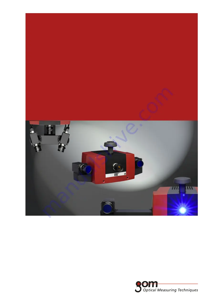
ATOS
User Manual - Hardware
ATOS COMPACT SCAN 5M, 2M
With Camera Supports 300 mm, 500 mm and SO
COMPACT
SCAN