background image

GF-DIO MANUAL


2012 


GF-DIO  

Digital Input/Output Board


Custom Cockpit System 

Congratulations on the purchase of a 
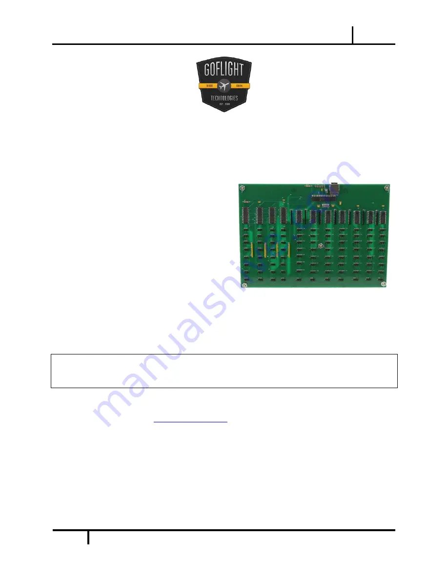
GF-

DIO Digital Input/Output Board

, a custom 

cockpit build essential.  This unit is part of 
the extensive family of GoFlight Custom 
Cockpit System modules.  The GF-DIO 
board is designed to maximize 
customization of any home built cockpit 
system by allowing unique placement of 
each and every knob, switch and rotary 
component. 


The steps below will assist in the installation, configuration and operation of the GF-DIO Board.  
Following these instructions will help any vpilot 

get up in the “virtual skies” as quickly as 

possible. 

Installing the latest GoFlight Technologies software 

Note 

– 

If you own other GoFlight hardware and have already installed the latest version of 

GoFlight software, you do not need to install the software again.  Simply skip Step 1 in the 
instruction manual below. 

STEP 1: 

1.  Get online and go to 

www.goflightinc.com


2. 

On the GoFlight home page click “Support” 

3. 

Click the link “GF Config Setup #.##” (# - reflects latest release) 

4. 

Click “Run” or “Save” and follow the instructions to install the software 

If the software installer detects that GoFlight software is already installed on the system, it will 
prompt it to be overwritten.  Click the Yes button to overwrite the existing version of GoFlight 
software.  This is useful if it is desired to keep the configuration settings for other GoFlight 

Summary of Contents for GF-DIO

Page 1: ...al skies as quickly as possible Installing the latest GoFlight Technologies software Note If you own other GoFlight hardware and have already installed the latest version of GoFlight software you do not need to install the software again Simply skip Step 1 in the instruction manual below STEP 1 1 Get online and go to www goflightinc com 2 On the GoFlight home page click Support 3 Click the link GF...

Page 2: ...ips between the electronic placements on the board and place any where you please STEP 3 Plugging in the hardware Example To connect the individual hardware components to the DIO Board use the cable assemblies that come with your DIO purchase On both the components and the board itself there are 3 pin connectors which simply plug into the connectors on the ends of the cable assemblies Each compone...

Page 3: ...er works like this first pin is the first position second pin is the ground wire and the third pin is the second position Then on the next wire the first pin repeats the second position the second pin remains as the ground and the third pin is the third position The pattern repeats throughout the DIO board STEP 5 Connecting the GF DIO Board Now the GF DIO Board must be connected to the computer Wi...

Page 4: ...ted to the board Once the switch is flipped a box will appear in use on the right side corresponding to each numbered position on the board Click on the Cockpit Functions and use the pull down menu to select the unique function for that switch You can see a screen shot of GF Config below and what it will look like with the GF DIO Board connected ready for configuration Below the Input section on t...

Page 5: ...ng the desired switch to be programmed Then select Key Sequence in the Input Function 1 Box in the GF Config program Now use the keyboard to set the keystrokes for the switch The screenshot below shows an example of what this process looks like Congratulations The steps to configure the GF DIO Board have been completed Once every switch has been configured the unit is ready to fly ...

Page 6: ... liability under this warranty is limited to the repair and or replacement of the defect or defective part and does not include shipping expenses This warranty does not apply if in the determination of GoFlight this product has been damaged by accident abuse improper usage or as a result of service or modification by anyone other than GoFlight NO OTHER WARRANTIES ARE EXPRESSED OR IMPLIED INCLUDING...

Reviews: