USER MANUAL
GUARDIAN
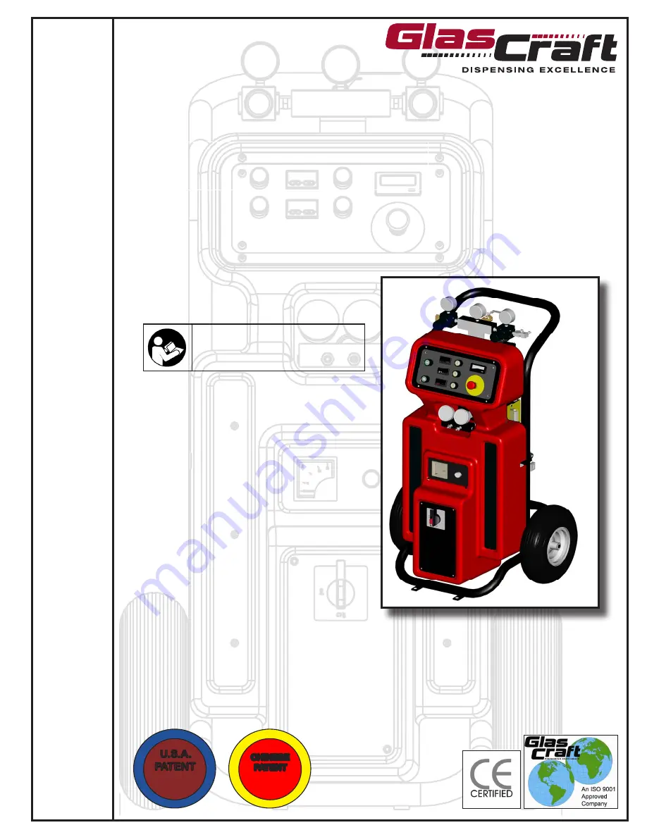
A6-6000
Dispensing System
TH
IS
E
Q
U
IP
ME
NT IS PRO
TE
C
T
E
D
B
Y
CHINESE
PATENT
ZL 200630130159.1
TH
IS
E
Q
U
IP
ME
NT IS PRO
TE
C
T
E
D
B
Y
U.S.A.
PATENT
D546,840
Important Safety Instructions
Read all warnings and instructions in
this manual. Save these instructions.
For use with non-flammable foam and polyurea.
Not for use in explosive atmospheres.
Summary of Contents for GUARDIAN A6-6000
Page 25: ...23 REVISION E Section 3 General Information Assembly Drawings 23675 XX Unit Assembly...
Page 26: ...24 REVISION E Section 3 General Information Assembly Drawings 23675 XX Unit Assembly...
Page 32: ...Section 3 General Information Sub Assembly Drawings 30 REVISION D 23450 XX Hybrid Assembly...