


© 2016 GeoVision, Inc. All rights reserved.
Under the copyright laws, this manual may not be copied, in whole or in part,
without the written consent of GeoVision.
Every effort has been made to ensure that the information in this manual is
accurate. GeoVision, Inc. makes no expressed or implied warranty of any kind
and assumes no responsibility for errors or omissions. No liability is assumed
for incidental or consequential damages arising from the use of the information
or products contained herein. Features and specifications are subject to
change without notice.
Note:
No memory card slot or local storage function for Argentina.
GeoVision, Inc.
9F, No. 246, Sec. 1, Neihu Rd.,
Neihu District, Taipei, Taiwan
Tel: +886-2-8797-8377
Fax: +886-2-8797-8335
http://www.geovision.com.tw
Trademarks used in this manual:
GeoVision
, the
GeoVision
logo and GV
series products are trademarks of GeoVision, Inc.
Windows
is the registered
trademark of Microsoft Corporation.
April 2016
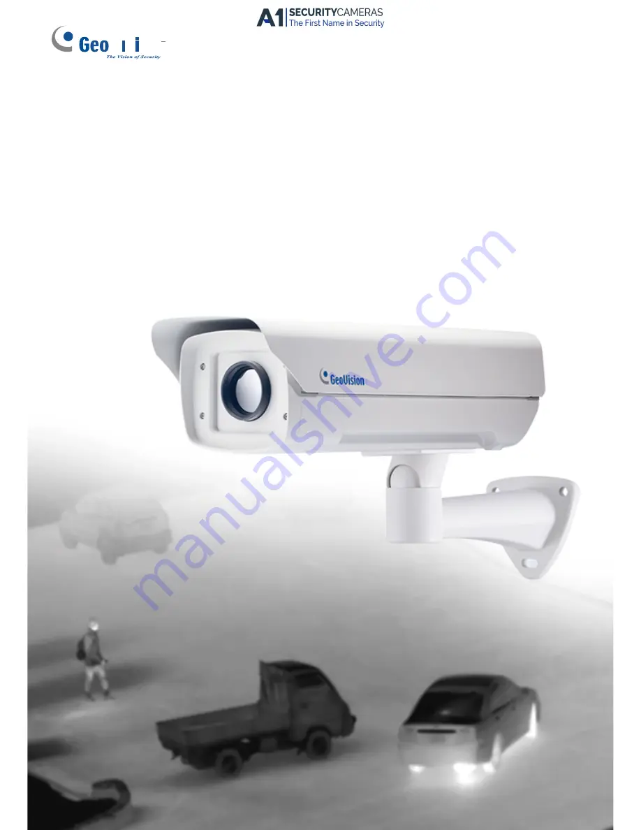
Quick Start Guide
GV-Thermal IP Camera
Before attempting to connect or operate this product,
please read these instructions carefully and save this manual for future use.
TMV10-
QG-
A
Available from A1 Security Cameras
www.a1securitycameras.com email: [email protected]


