background image


INSTALLATION AND OPERATION MANUAL 

KBMK SERIES 


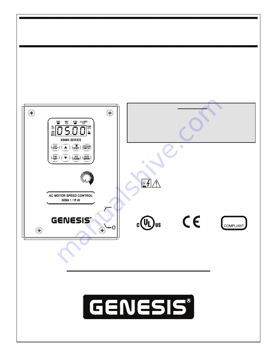
Adjustable Frequency Drives 

for 1/8 HP thru 1 HP 3-Phase AC Motors Rated 208 – 230 VAC, 50/60 Hz 


NEMA-1 / IP-40 


Operate from 115* and 208/230 Volt 50/60 Hz AC Line 

 Variable Speed / Soft-Start with Electronic Motor Overload Protection

1


*IMPORTANT 


This drive is factory set for: 
1. 60 Hz Motors. 
    

For 50 Hz motors, see Figure 12, on page 16. 


2. 208/230 Volt AC Line Input. 

     For 115 Volt AC line input, see Section 7, on page 14. 


 See Safety Warning, on page 5. 


I


LISTED 

IND. CONT. 

EQ. – 70ZA 

RoHS


This Manual Covers Models KBMK-24D and KBMK-24DF

2


The information contained in this manual is intended to be accurate.  However, the 

manufacturer retains the right to make changes in design which may not be included herein. 


Notes:


1.

 UL approved as an electronic overload protector for motors.  

2. 

Model KBMK-24DF contains a built-in 

AC line Class A RFI (EMI) filter which meets CE Council Directive 89/336/EEC Industrial Requirement.  For Class 
B Residential Requirement, install the KBRF-300 RFI (EMI) Filter (Part No. 9484).


Automation and Control


COPYRIGHT © 2008 KB Electronics, Inc. 

(see back cover) 

Summary of Contents for KBMK Series

Page 1: ...14 See Safety Warning on page 5 I LISTED IND CONT EQ 70ZA 2 RoHS This Manual Covers Models KBMK 24D and KBMK 24DF 2 The information contained in this manual is intended to be accurate However the man...

Page 2: ...ssignment 32 13 Preset Frequency Selection with 2 Wire Start Stop Programming 33 14 Preset Frequency Selection 34 15 Up Down Frequency Control Programming 35 16 Accel Decel 2 Programming 35 17 Forward...

Page 3: ...nnections 42 33 Analog Input 2 Signal Current Following Connections 43 34 Analog Outputs 1 and 2 Gain 44 35 Analog Outputs 1 and 2 Connections 44 36 Remote Unidirectional Speed Potentiometer Connectio...

Page 4: ...ed that both Feed Through Bushings be used to connect the drive If signal wiring for the Multi Function Output Relay contacts or for a Remote Speed Potentiometer is required it is recommended that the...

Page 5: ...electrical connections fusing or other current protection and grounding can reduce the chance of electrical shocks and or fires in this product or products used with this product such as electric moto...

Page 6: ...es Adjustable RMS Current Limit and I2 t Motor Overload Protection Flux Vector Compensation with Static Auto Tune and Boost provides high torque and excellent load regulation over a wide speed range P...

Page 7: ...LINE INPUT VOLTAGE SELECTION 115 230 Volts AC J1 TABLE 1 OPTIONAL ACCESSORIES Description Part No On Off AC Line Switch Panel mounted Used to turn the power on and off to the drive 9683 IODA Input Ou...

Page 8: ...5 3 Dependent on motor performance 4 Do not operate the drive outside the specified AC line input voltage operating range FIGURE 2 KEYPAD LAYOUT WITH BUILT IN SPEED POTENTIOMETER Notes 1 The JOG LCL R...

Page 9: ...9 FIGURE 3 COVER LAYOUT I FIGURE 4 DRIVE LAYOUT...

Page 10: ...oad conditions If the motor is operated in this manner for an extended period of time it is recommended that the unloaded motor current be checked from 2 15 Hz 60 450 RPM to ensure motor current does...

Page 11: ...as an overload protector for motors 5 MOUNTING INSTRUCTIONS It is recommended that the drive be mounted vertically on a flat surface with adequate ventilation Leave enough room below the drive to allo...

Page 12: ...6 1 AC LINE INPUT CONNECTION See Warning on page 11 Connect the AC line input to Terminal Block TB1 Terminals L1 L2 as shown in Figure 8 See Table 2 on page 7 Application Note If operation with a Gro...

Page 13: ...set to 0001 and a fault occurs while the drive is in the Run Mode the relay contacts will change state The Normally Open N O contact closed in the Run Mode will open and the Normally Closed N C contac...

Page 14: ...age to the drive which has been installed in the equipment the following procedure is recommended A typical hi pot test setup is shown in Figure 11 on page 15 All drives have been factory hi pot teste...

Page 15: ...n properly setup and all connections completed the start up procedure can begin If the AC power has been properly brought to the drive the LEDs on the front cover will indicate the drive s status as d...

Page 16: ...ote Operation Used to enter Program Mode and Display Mode If the key is pressed while Set Frequency is displayed the previously entered Function Number will be shown If the key is pressed while Functi...

Page 17: ...mps FIGURE 14 FLOW CHART TO PROGRAM SET FREQUENCY FROM 5 00 Hz TO 43 21 Hz DRIVE IN STOP MODE If Function No 2 01 is set to 0000 frequency change requires ENTER Throughout this sequence you must proce...

Page 18: ...l Time Function No 3 03 is 1 5 seconds The minimum setting of Accel is 0 1 seconds therefore the left digits must be changed first since an Accel setting of 000 0 is not allowed FIGURE 16 FLOW CHART T...

Page 19: ...factory setting of Custom Units Significant Digits Function No 4 01 is 0100 3 The factory setting of Custom Units Display Function No 4 02 is Whole Numbers 0000 4 The Custom Unit setting 012 0 will be...

Page 20: ...on No 4 06 set to 0001 Low Voltage Trip Indicates that the AC line input voltage is below the Undervoltage Trip Point specified in Table 3 on page 8 Low Voltage Recovery Indicates that a Low Voltage T...

Page 21: ...vailable contact our Sales Department Programming Mode When the drive is put into the Programming Mode see Figure 19 a Function No will be displayed A Function No consists of a Group No digits on the...

Page 22: ...dard GFCI 0002 GFCI Operation with Sensitive GFCI 0000 0 05 Motor Frequency Hz 3 4 30 240 60 50 0 06 Motor Nameplate Voltage Drive Output 5 0 100 0 100 6 Notes 1 Factory Setting is the drive rated out...

Page 23: ...Start with Ride Through Set by Function No 1 06 0002 Auto Start After Undervoltage Fault Clears 0003 Auto Start All Faults Except Short Circuit Fault 3 0004 Auto Start All Faults Except I2 t I t and S...

Page 24: ...ion Range Code Factory Setting 3 00 Stored Set Frequency Hz 0 00 240 0 5 00 3 01 Lower Frequency Limit Hz 0 00 240 0 0 00 3 02 Upper Frequency Limit Hz 1 0 00 240 0 60 0 50 0 3 03 Accel Time Seconds 2...

Page 25: ...OUP 5 Onboard Multi Function Output Relay Operating Mode Function No Description Range Code Factory Setting 5 00 Relay Operation Mode 0000 Run 0001 Fault 1 0002 Target Frequency Function No 5 01 Funct...

Page 26: ...00 7 08 Preset Frequency 2 Hz 0 00 240 0 10 00 7 09 Preset Frequency 3 Hz 0 00 240 0 20 00 7 10 Preset Frequency 4 Hz 0 00 240 0 25 00 7 11 Preset Frequency 5 Hz 0 00 240 0 30 00 7 12 Preset Frequency...

Page 27: ...in Function No 8 04 and deactivate below the setting in Function No 8 04 minus the setting in Function No 8 05 3 The Multi Function Output Relay will activate below the setting in Function No 8 04 and...

Page 28: ...JOG LCL REM Command Off 1 JOG LCL REM Command On 4 0 N A 1 Preset Frequency 1 5 0 N A 1 Preset Frequency 2 6 0 N A 1 Preset Frequency 3 7 0 N A 1 Preset Frequency 4 8 0 N A 1 Preset Frequency 5 9 0 N...

Page 29: ...ay to no longer be illuminated as a guaranteed power off condition TABLE 8 LED DESCRIPTIONS LED Description Illuminates when Jog is selected Flashes when the drive is set for Remote Signal Operation I...

Page 30: ...urrent signal output from the IODA has been opened Communication Error Err4 indicates that communication between the drive and the IODA has failed WARNING Do not depend on the Status LEDs or the 4 Dig...

Page 31: ...ce Trip 2 Illuminated Notes 1 When a Communication Error occurs the drive s 4 Digit Display will show Err4 2 When a Current Source Trip occurs the drive s 4 Digit Display will show CS t FIGURE 20 IODA...

Page 32: ...26 Relay 2 N O 27 Relay 2 Common 28 Relay 2 N C Notes 1 Multi Function Input Terminals 1 7 can be programmed for 7 Preset Frequencies Up or Down Frequency Command Accel Decel 2 Forward Stop Reverse S...

Page 33: ...tion No 3 00 of 5 00 Hz If the 8th Preset Frequency is not required set Function No 3 00 to 00 00 Hz Note For Preset Frequency Operation only the drive does not have to be reprogrammed for External Co...

Page 34: ...7 15 range is 0 01 30 00 Hz factory set to 1 00 Hz Free Running Operation Close the Start Stop Switch or Contact to put the drive into the Run Mode When the Up Switch or Contact is closed the drive ou...

Page 35: ...econdary Accel Decel Time setting which can be remotely selected with a normally open switch or contact connected to a Multi Function Input Terminal See Table 16 for drive programming See Figure 24 on...

Page 36: ...t the common of the switches or contacts to any available common terminal 8 12 14 16 18 20 22 Operation When the Forward Stop Switch or Contact is closed the drive will run in the forward direction Wh...

Page 37: ...the External Fault has been Cleared 1 If the drive is set for Manual Start Mode 0000 factory setting Manual Start with Ride Through 0001 or Auto Start After Undervoltage Fault Clears 0002 it will have...

Page 38: ...MING Function No Code 7 03 Multi Function Input Terminal 4 0009 Reset Factory setting FIGURE 27 RESET CONNECTIONS A7 2 WIRE AND 3 WIRE START STOP A remote Start Stop Switch or Contact can be used to s...

Page 39: ...tory set for N O Start 0010 Set the respective Multi Function Input Terminal Function Nos 7 00 7 06 which will be used for N C Stop to 0011 In Figure 29 Multi Function Input Terminal 6 has been arbitr...

Page 40: ...ad using the JOG LCL REM Key The following functions can be switched between remote and local Keypad operation Start Stop Forward Reverse Analog Signal Inputs 1 and 2 and Up Down Frequency Control Set...

Page 41: ...nnections MAX1 Trimpot If the Analog Input 1 signal is higher than 5 Volts use Trimpot MAX1 to attenuate it Apply the maximum signal input and set the drive for full speed output and observe the displ...

Page 42: ...ing Current Signal Input Set Jumper J1 to the CUR position PWM Signal Input Set Jumper J1 to the VOLT position factory setting Connect the signal input to Terminal 21 and the common to Terminal 22 Con...

Page 43: ...put 2 Response Time mSec 2 100 Set to the Desired Time Factory setting FIGURE 33 ANALOG INPUT 2 SIGNAL CURRENT FOLLOWING CONNECTIONS MAX2 Trimpot and Jumper J1 A9 ANALOG SIGNAL OUTPUT Two analog signa...

Page 44: ...0 Motor Frequency 0001 Set Frequency 0002 Motor Voltage 0003 Bus Voltage 0004 Motor Current 8 07 Analog Output 1 Gain 0 200 Set to the Desired Gain 8 08 Analog Output 2 Mode 0000 Motor Frequency 0001...

Page 45: ...8 for drive programming See Figure 36 on page 46 for connections Operation When the Start Stop Switch or Contact is closed the drive will be in the Run Mode Rotate the potentiometer clockwise to incre...

Page 46: ...to start the drive At 50 rotation the potentiometer is set for zero speed Rotating the potentiometer clockwise will increase motor frequency in the forward direction Rotating the potentiometer counter...

Page 47: ...p Command 7 04 Multi Function Input Terminal 5 0010 N O Start Factory setting FIGURE 38 REMOTE SPEED POTENTIOMETER WITH FORWARD REVERSE CONNECTIONS MAX2 Trimpot and Jumper J1 A11 MULTI FUNCTION OUTPUT...

Page 48: ...mmed for Run Fault Target Frequency Frequency Threshold Level 8 04 8 05 Frequency Threshold Level 8 04 8 05 I2 t or I t Fault Load Loss External Fault and Motor Overload See Table 32 on page 49 for dr...

Page 49: ...Open Collector Output 2 0000 Run 0001 Fault 0002 Target Frequency 0003 Frequency Threshold Level 8 04 8 05 0004 Frequency Threshold Level 8 04 8 05 0005 I2 t or I t Fault 0006 Load Loss 0007 External...

Page 50: ...50 NOTES...

Page 51: ...51 NOTES...

Page 52: ...damage including injury to any person caused by items of our manufacture or sale Some states do not allow certain exclusions or limitations found in this warranty and therefore they may not apply to...

Page 53: ...r one year it is necessary to recondition the power supply bus capacitors To recondition the bus capacitors apply the AC Line with the drive in the Stop Mode for a minimum of one hour Not following th...

Reviews: