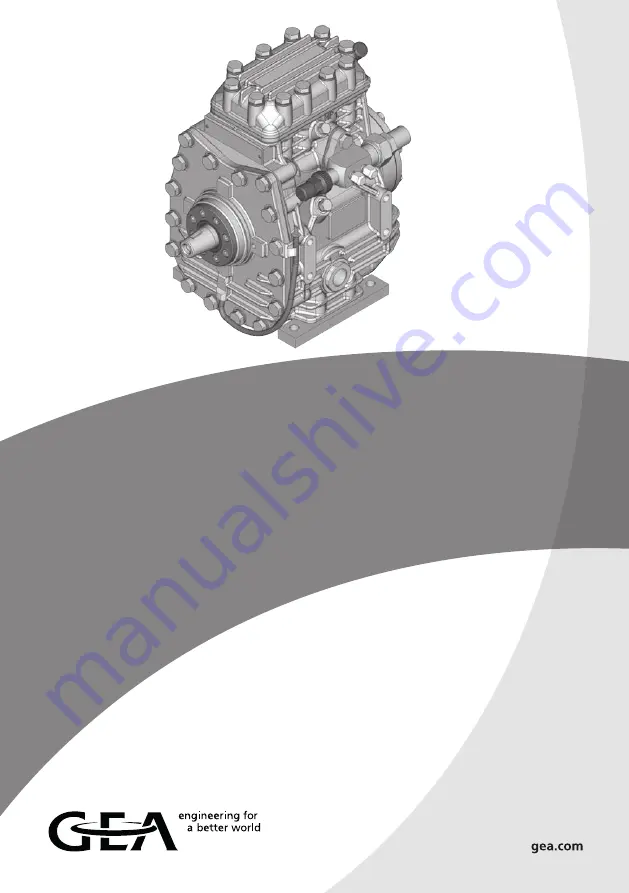
background image

GEA Bock FK30

Assembly instructions

09705-01.2018-Gb

Translation of the original instructions

FK30/235 N 

FK30/275 N 

FK30/325 N 

FK30/235 K 

FK30/275 K 

FK30/325 K 

FK30/235 TK 

FK30/275 TK 

FK30/325 TK

FKX30/235 N 

FKX30/275 N 

FKX30/325 N 

FKX30/235 K 

FKX30/275 K 

FKX30/325 K 

FKX30/235 TK  FKX30/275 TK  FKX30/325 TK

Summary of Contents for FK30

Page 1: ... Translation of the original instructions FK30 235 N FK30 275 N FK30 325 N FK30 235 K FK30 275 K FK30 325 K FK30 235 TK FK30 275 TK FK30 325 TK FKX30 235 N FKX30 275 N FKX30 325 N FKX30 235 K FKX30 275 K FKX30 325 K FKX30 235 TK FKX30 275 TK FKX30 325 TK ...

Page 2: ... use of the compressor can lead to serious or fatal injury Observe the safety instructions contained in these instructions These instructions must be passed onto the end customer along with the unit in which the compressor is installed GEA Bock GmbH 72636 Frickenhausen Manufacturer Contact GEA Bock GmbH Benzstrasse 7 72636 Frickenhausen Germany Phone 49 7022 9454 0 Fax 49 7022 9454 137 info gea co...

Page 3: ...ation 4 3 V belt drive 4 4 Main bearing load 4 5 Installation of electromagnetic clutch assembly 4 6 Pipe connections 4 7 Pipes 4 8 Operating the shut off valves 4 9 Operating mode of the lockable service connections 4 10 Suction pipe filter 5 Commissioning 15 5 1 Preparations for start up 5 2 Pressure strength test 5 3 Leak test 5 4 Evacuation 5 5 Refrigerant charge 5 6 Oil level check 5 7 Shaft ...

Page 4: ...amage INFO Important information or tips on simplifying work WARNING Inadequately qualified personnel poses the risk of accidents the consequence being serious or fatal injury Work on compressors is therefore reserved for personnel which is qualified to work on pressurized refrigerant systems For example a refrigeration technician refrigeration mechatronic engineer As well as professions with comp...

Page 5: ...U Pressure Equipment Directive Commissioning is permissible only if the compressor has been installed in accordance with these assembly instructions and the entire system into which it is integrated has been inspected and approved in accordance with legal regulations 1 4 Intended use WARNING Risk of accidents Refrigerating compressors are pressurised machines and as such call for heightened cautio...

Page 6: ...and efficiency are concerned Compact two cylinder compressor in single row Three capacity ranges Lightweight aluminum design Lubricating oil pump with oil pressure relief valve independent of rotational direction Variable connection and fixing options Fig 1 2 1 Brief description Fig 2 Oil sight glass Valve plate Cylinder cover Shaft end Shaft seal Suction shut off valve Oil pump Dimension and conn...

Page 7: ... 4 Machine number 5 Factory filled oil type Fig 3 2 2 Name plate example 2 3 Type key example K specially for air conditioning N specially for air conditioning or normal cooling TK specially for deep freezing X Ester oil charging HFC refrigerant e g R134a R407C Designs Swept volume Size Ester oil charging Series 1 2 3 4 5 AS12345A020 19 28bar Observe the limits of application diagrams FKX30 325N 2...

Page 8: ... be selected as design or continuous operating points Max permissible discharge end temperature 140 C Max permissible ambient temperature 100 C Max permissible switching frequency 12 x h A minimum running time of 2 min at equilibrium continuous operation must be achieved Avoid continuous operation near the threshold Should the com pressor happen to be used near the thresholds we recommend the use ...

Page 9: ...perature C Suction gas temperature C Fig 4 Fig 5 20 30 50 70 80 20 10 10 0 20 30 t C o t C c 82 30 40 60 90 t 25 C oh toh 20 K R134a 20 30 50 20 10 10 0 20 t C o t C c 61 30 40 60 25 toh 20 K t 25 C oh R407C 3 4 1 Limits of application R134a N and K versions 3 4 N and K versions Models available FKX30 235 N FKX30 275 N FKX30 325 N FKX30 235 K FKX30 275 K FKX30 325 K Permissible rotation speeds N D...

Page 10: ... reduzierte Sauggastemperatur FK R22 tc t0 toh Dtoh Verdampfungstemperatur C Verflüssigungstemperatur C Sauggasüberhitzung K Sauggastemperatur C Uneingeschränkter Anwendungsbereich reduzierte Sauggastemperatur R22 TK 10 0 10 20 30 40 50 20 30 40 50 60 70 t C o t C c Dtoh 20K t 25 C oh 66 45 Max permissible operating pressure g high pressure side HP 28 bar Unrestricted application range Reduced suc...

Page 11: ...for running comfort operating safety and the service life of the compressor In the condition on delivery the compressor is provided with installa tion feet see Fig 8 Alternatively the compressor can also be bolted directly without installation feet on the substructure A a A a A max 30 max 2 minutes a max 15 continuous operation INFO New compressors are factory filled with inert gas Leave this ser ...

Page 12: ...romagnetic clutch secured to a shaft To absorb the magnetic field of the electromagnetic clutch the front bearing flange has a snug fit Ø 95 f7 see Fig 11 For the installation push the magnetic field on snugly and fasten with 2 cheese head screws M6 x 16 see Fig 12 Screw tightening torque 15 Nm Further assembly of the electromagnetic clutch according to the clutch manufacturer Bearing flange front...

Page 13: ...nd on the dimension The connection diameters of the shut off valves are designed for maximum compressor output The required pipe cross section must be matched to the capacity The same applies for non return valves Fig 13 Stepped internal diameters 4 6 Pipe connections Valve spindle seal 4 8 Operating the shut off valves Before opening or closing the shut off valve release the valve spindle seal by...

Page 14: ...nnection opened shut off valve opened The connection is not lockable and is provided for safety devices Service connection closed Connection closed Spindle Connection not lockable Connection not lockable Service connection open Spindle Connection open Compressor Compressor After activating the spindle generally fit the spindle protection cap again and tighten with 14 16 Nm This serves as a second ...

Page 15: ...or a corresponding safety standard while always observing the maximum permissible overpressure for the compressor 5 2 Pressure strength test The compressor has been tested in the factory for pressure integrity If however the entire system is to be subjected to a pressure integrity test this should be carried out in accordance with EN 378 2 or a corresponding safety standard without the inclusion o...

Page 16: ... it can be topped up in vapour form on the suction side or taking suitable precautions also in liquid form at the inlet to the evaporator 5 5 Refrigerant charge CAUTION Wear personal protective clothing such as goggles and protective gloves ATTENTION Avoid overfilling the system with refrigerant To avoid shifts in concentration zeotropic refrigerant blends must always be added to the refrigerating...

Page 17: ...pacities of all components must be compatible particularly evaporator and expansion valve Suction gas superheating at the evaporator output should be at least 7 10 K check setting of the expansion valve The system must reach a state of equilibrium Particularly in critical systems e g several evaporator points suitable measures e g use of liquid traps solenoid valve in the liquid line etc are recom...

Page 18: ...ressor and secure it to prevent a restart Relieve compressor of system pressure Prevent air from infiltrating the system After maintenance has been performed Connect safety switch Evacuate compressor Release switch lock Fig 18 As changing the shaft seal involves opening the refrigerant circuit this is recommended only if the seal is losing refriger ant Replacing the shaft seal is described in the ...

Page 19: ...he shut off valve on the compressor Drain the refrigerant it must not be discharged directly into the environment and dispose of it according to the regulations When the compressor is depres surised undo the fastening screws of the shut off valves Remove the compressor using an appropri ate hoist Dispose of the oil inside in accordance with the valid national regulations 6 Maintenance 6 6 Extract ...

Page 20: ...t gas side of the compressor housing see Chap 9 Connect the thermal protection thermostat in series with the control line Technical Data Switching voltage max 24 V DC Switching current max 2 5 A at 24 V DC Switch off temperature 145 C 5 K Switch on temperature approx 115 C 7 1 Thermal protection thermostat Art No 07595 ...

Page 21: ...h Oil charge Ltr Inertia moment of the driving unit kgm 2 Lubri c ation Oil pump FK30 235 2 233 20 3 25 0 16 5 8 22 7 8 2 0 0 0028 Forced lubrication Rotation independent FK30 275 277 24 1 22 7 8 28 1 1 8 FK30 325 325 28 3 22 7 8 28 1 1 8 Connections The technical data for the different designs K N and TK are identical The compressor type data therefore do not mention these additions ...

Page 22: ...22 D GB F I Tr Ru 09705 01 2018 DGbFITrRu 9 Dimensions and connections Shaft end Centre of gravity Fig 19 Dimensions in K Design FK30 235 Dimensions in mm only FK30 235 Leak oil drain hose both sides ...

Page 23: ...arge side not lockable 7 16 UNF B1 Connection discharge side lockable 7 16 UNF C Connection oil pressure safety switch OIL 1 8 NPTF D Connection oil pressure safety switch LP 1 4 NPTF E Connection oil pressure gauge 1 8 NPTF F Oil drain M22 x 1 5 G Opt connection for oil sump heating 1 M22 x 1 5 H Oil charge plug 1 4 NPTF K Sightglass 1 1 8 18 UNEF L Connection thermal protection thermostat 1 8 NP...

Page 24: ...dards referenced A partly completed machine may only be put into operation when it has been established that the machine into which the partly completed machine is to be installed conforms to the regulations of the Machinery Directive 2006 42 EC The manufacturer undertakes to transmit electronically the special documentation required by individual states for partly completed machinery upon request...

Page 25: ... any questions about installation operation and accessories please contact our technical service or specialist wholesaler and or our representative The GEA service team can be contacted by phone with a toll free hotline 00 800 800 000 88 or via e mail info gea com Yours faithfully GEA Bock GmbH Benzstraße 7 72636 Frickenhausen Germany 11 Service ...

Page 26: ...one 49 0 7022 9454 0 Fax 49 0 7022 9454 137 info gea com gea com GEA Group is a global engineering company with multi billion euro sales and operations in more than 50 countries Founded in 1881 the company is one of the largest providers of innovative equipment and process technology GEA Group is listed in the STOXX Europe 600 index ...

Reviews: