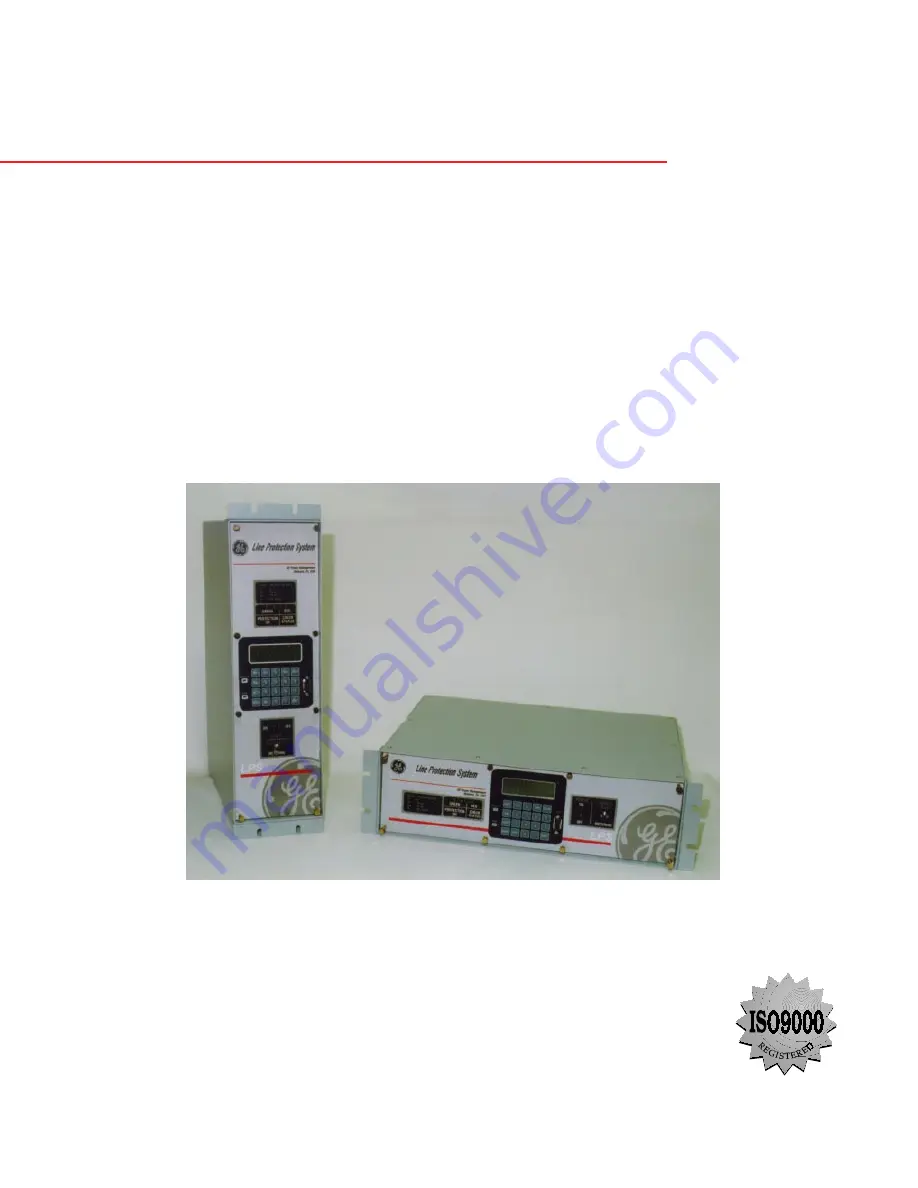
background image

LPS-O

Line Protection™ System

Instruction Manual

LPS-O Revision: V0001.03AA20

Manual P/N: GEK-106266A

Copyright © 2001 GE Power Management

GE Power Management

215 Anderson Avenue, Markham, Ontario 

Canada L6E 1B3

Tel: (905) 294-6222   Fax: (905) 201-2098

Internet: http://www.GEindustrial.com/pm/

Note: All relays must be powered up at least once per year to

avoid deterioration of electrolytic capacitors and
subsequent relay failure.

Manufactured under an

ISO9002 Registered system.

g

GE Power Management

Summary of Contents for LPS-O

Page 1: ...r Management 215 Anderson Avenue Markham Ontario Canada L6E 1B3 Tel 905 294 6222 Fax 905 201 2098 Internet http www GEindustrial com pm Note All relays must be powered up at least once per year to avoid deterioration of electrolytic capacitors and subsequent relay failure Manufactured under an ISO9002 Registered system g GE Power Management ...

Page 2: ......

Page 3: ...hould further information be desired or should particular problems arise which are not covered sufficiently for the pur chaser s purpose the matter should be referred to the General Electric Company To the extent required the products described herein meet applicable ANSI IEEE and NEMA standards but no such assurance is given with respect to local codes and ordinances because they vary greatly ...

Page 4: ......

Page 5: ... FLASH MEMORY 1 12 1 5 2 LINE OVERLOAD 1 12 1 5 3 CURRENT UNBALANCE DETECTION 1 12 1 5 4 FAULT REPORT 1 12 1 5 5 OSCILLOGRAPHY 1 12 1 5 6 PLAYBACK 1 13 1 5 7 SEQUENCE OF EVENTS 1 13 1 5 8 EQUIPMENT DUTY 1 13 1 5 9 SELECTABLE GROUPS OF SETTINGS 1 13 1 5 10 TIME SYNCHRONIZATION 1 14 1 5 11 TRIP BUS CHECK 1 15 1 5 12 TRIP CIRCUIT MONITOR 1 15 1 5 13 ALARMS 1 15 1 5 14 METERING 1 16 1 5 15 BREAKER CON...

Page 6: ... 15 2 3 8 VOLTAGE 2 18 2 3 9 LINEPICKUP 2 19 2 3 10 REMOTEOPEN 2 21 2 3 11 LINEOVRLD 2 22 2 3 12 SCHEME TIMERS 2 23 2 3 13 LINE INFO 2 23 2 3 14 OS BLOCKING 2 24 2 3 15 OS TRIPPING 2 25 2 3 16 NONCRIT_AL 2 27 2 3 17 OUTPUTS 2 28 2 4 INVERSE CURVES 2 4 1 INVERSE CURVE 2 29 2 4 2 VERY INVERSE CURVE 2 30 2 4 3 EXTREMELY INVERSE CURVE 2 31 2 5 REFERENCE TABLES 2 5 1 INDEX NUMBERS 2 32 2 5 2 PROTECTION...

Page 7: ...MMUNICATIONS OPTIONAL 4 5 a HARDWARE SETUP 4 6 b PC SOFTWARE SETUP 4 6 c LOAD START LPSO LINK 4 6 d SET LOCAL PC CONFIGURATION 4 6 e CREATE TEST UNIT DESCRIPTION 4 6 f RELAY SETUP 4 7 g LOGGING INTO THE RELAY 4 7 h SETTING CHANGES 4 7 i ENTERING TEST MODE 4 8 j EXITING TEST MODE 4 8 k INITIAL TEST SETUP 4 8 4 2 GENERAL RELAY TESTS 4 2 1 T1 RELAY STATUS AND DISPLAY TESTING 4 9 a STATUS CHECK 4 9 b ...

Page 8: ...UNCTIONAL TESTS USER SETTINGS 6 1 LPS O FUNCTIONAL TESTS 6 1 1 DESCRIPTION 6 1 a MEASURING UNIT TESTS 6 1 b ZONE PHASE REACH TESTS 6 1 6 1 2 DRAWINGS AND REFERENCES 6 2 a DRAWINGS 6 2 b REFERENCE 6 2 6 1 3 GENERAL INSTRUCTIONS 6 2 6 2 MEASURING UNIT TESTS 6 2 1 T1 FAULT DETECTOR TEST 6 3 6 2 2 T2 IT TRIP SUPERVISION TEST 6 3 6 2 3 T3 IB BLOCKING SUPERVISION TEST 6 3 6 2 4 T4 GROUND DIRECTIONAL TRI...

Page 9: ...ST 8 12 8 1 17 KEYPAD DISPLAY INTERFACE TEST 8 13 8 1 18 DIGITAL OUTPUT TEST 8 14 8 1 19 PLAYBACK 8 15 8 1 20 CHANGE PASSWORD 8 17 8 1 21 ENABLE DISABLE PASSWORDS 8 17 8 1 22 RESET DATA 8 17 8 1 23 ADJUST CONTRAST 8 17 8 2 INFORMATION 8 2 1 DESCRIPTION 8 18 8 2 2 REQUEST STATUS INFORMATION 8 18 8 2 3 REQUEST FAULT INFORMATION 8 19 8 2 4 REQUEST PRESENT VALUES 8 20 8 2 5 CONTACT CONVERTER STATUS 8 ...

Page 10: ... 1 INTRODUCTION 10 1 1 DESCRIPTION 10 1 10 1 2 STARTING THE PROGRAM FOR THE FIRST TIME 10 1 10 1 3 STARTING PROGRAM AFTER THE FIRST TIME 10 2 10 2 TEST CALCULATIONS 10 2 1 DESCRIPTION 10 3 10 2 2 ENTERING INPUT QUANTITIES 10 3 10 2 3 ENTERING A VALUE 10 4 10 2 4 SELECTING A VALUE 10 5 10 2 5 M1 PHASE UNITS ZONE 1 10 5 10 2 6 MT PHASE UNITS ZONE 2 10 6 10 2 7 M3 PHASE UNITS ZONE 3 10 6 10 2 8 M4 PH...

Page 11: ...LLATION 11 4 a INSTALLING FROM PRODUCTS CD 11 4 b INSTALLING FROM THE INTERNET 11 8 11 3 USING LPSO LINK 11 3 1 STARTUP 11 9 11 3 2 MENU BAR 11 9 11 3 3 TOOL BAR 11 10 11 3 4 STATUS BAR 11 10 11 4 SETTING UP YOUR HOST MACHINE 11 4 1 DESCRIPTION 11 11 11 4 2 COM PORT SETUP 11 11 11 4 3 MODEM SETUP 11 11 11 4 4 PRINTER SETUP 11 12 11 4 5 DEVICE SETUP 11 13 11 4 6 HOW TO ADD A DEVICE 11 13 11 5 CONNE...

Page 12: ...5 11 8 12 CONTACT STATUS REPORT 11 25 11 8 13 LUI PASSWORD REPORT 11 25 11 8 14 OPEN REPORT 11 25 11 8 15 SAVE REPORT 11 26 11 8 16 PRINT REPORT 11 26 11 9 LOGGING 11 9 1 SESSION LOG 11 27 11 9 2 TURN OFF 11 27 11 9 3 CURRENT SESSION LOG 11 27 11 9 4 OPEN SESSION LOG 11 27 11 9 5 ARCHIVAL 11 27 11 9 6 ARCHIVE 11 28 11 9 7 RETREIVE 11 28 12 ASCII COMMUNICATIONS 12 1 INTRODUCTION 12 1 1 DESCRIPTION ...

Page 13: ...RESSION BUILDER LOGIC 13 13 13 4 4 COMPILING AND DOWNLOADING XPRESSION BUILDER LOGIC 13 16 13 4 5 BREAKER FAILURE EXAMPLE 13 16 A FREQUENTLY ASKED QUESTIONS A 1 FREQUENTLY ASKED QUESTIONS B TABLES AND FIGURES B 1 TABLES B 1 1 LIST OF TABLES B 1 B 2 FIGURES B 2 1 LIST OF FIGURES B 2 C KEYPAD MENUS C 1 KEYPAD MENUS C 1 1 SET MENU C 1 C 1 2 ACT KEYPAD MENU C 2 C 1 3 INF KEYPAD MENU C 3 D WARRANTY D 1...

Page 14: ...x LPS O Line Protection System GE Power Management TABLE OF CONTENTS ...

Page 15: ...change settings and put the relay into test mode can be found in Sec tion 4 1 7 SETTING CHANGES on page 4 3 Complete instructions on how to operate the keypad are found in Chapter 8 LOCAL USER INTERFACE GE Power Management contact information GE Power Management 215 Anderson Avenue Markham Ontario Canada L6E 1B3 Telephone 905 294 6222 Fax 905 201 2098 E mail info pm indsys ge com Home Page www GEi...

Page 16: ...on page 11 4 to load LPSO Link onto the PC 1 1 4 PASSWORDS WITH LPSO LINK The LPSO Link program requires the use of passwords to obtain information from the relay to change Set tings or to perform Actions The relay is shipped from the factory with the following communications pass words VIEW VIEW SETTINGS SETTING ACTIONS CONTROL MASTER MASTER NOTE The exclamation point following the letters is par...

Page 17: ...hase Distance and Ground Overcurrent Relay with Out of Step Tripping Software B Revision Level Tripping Logic 3 Three Phase Tripping Logic Current Rating 1 1 Ampere rated current 5 5 Ampere rated current Series Caps U For applications without series capacitors Battery Voltage 0 48V DC battery voltage 1 110 125 V DC battery voltage 2 220 250 V DC battery voltage Trip Outputs 1 SCR trip outputs cont...

Page 18: ...he LPS O can be used to complement Generator Protection relay systems like the DGP and SR489 Also the LPS O may be used for line protection It can provide three zones of phase distance and ground overcurrent protection for either solidly grounded or resistance grounded systems where ground distance func tions may not provide reliable protection The external connections for the LPS O are shown in t...

Page 19: ... Mho phase distance functions with time delay Zone 2 Pilot Zone 3 Variable Mho phase distance functions with time delay and Ground directional overcurrent functions consisting of IPT Ground Trip overcurrent NT Negative Sequence Directional Trip IPB Ground Block overcurrent NB Negative Sequence directional block Zone 3 3 Variable Mho phase distance functions with time delay Zone 4 3 Variable Mho ph...

Page 20: ...3 XPRESSION BUILDER 1 3 2 CONFIGURABLE INPUTS All of the contact converters Digital Inputs in the LPS O are user configurable However each LPS O relay is shipped with the Default Contact Converter Assignments shown in Table 1 3 LPS O DEFAULT CONTACT CONVERTER ASSIGNMENTS below and the elementary diagram Figure 1 11 ELEMENTARY DIAGRAM on page 1 25 1 3 3 CONFIGURABLE OUTPUTS All of the output relays...

Page 21: ... LPS O DEFAULT OUTPUT CONTACT ASSIGNMENTS RELAY DESCRIPTION MNEMONIC INDEX NUMBER T1 TRIP CIRCUIT 1 TRIP 33 T2 TRIP CIRCUIT 2 TRIP 33 T3 TRIP CIRCUIT 3 TRIP 33 T4 TRIP CIRCUIT 4 TRIP 33 T5 SPARE T6 SPARE A1 MANUAL CLOSE BREAKER 1 MNCLS1 58 A2 MANUAL CLOSE BREAKER 2 MNCLS2 59 A3 BREAKER FAILURE INITIATE 1 TRIP 33 A4 BREAKER FAILURE INITIATE 2 TRIP 33 A5 RECLOSE INITIATE 1 RI 37 A6 RECLOSE INITIATE ...

Page 22: ...line are de energized open When one or more phases of protected line are open PTFF is disabled Figure 1 1 PTFF LOGIC DIAGRAM If AC potential is lost for any reason including a blown fuse or fuses and there is no disturbance on the power system so that the fault detector has not operated AND1 produces an output that causes timer TL1 to time out and produce a PTFF output via OR2 The output of OR2 is...

Page 23: ...ne Pickup out of service Timer TL403 is provided for those cases where simultaneous high speed reclosing is employed at both ends of the line and where the I1 function must be set to pick up below the maximum load current that can occur at that time TL403 then allows time for the voltage to return to normal and take Line Pickup out of service before it can trip on load current If simultaneous high...

Page 24: ... allowed to produce an output when the remote breaker opens provided there is sufficient charging current to operate one or more of the three charging current detectors that are the inputs to OR1 The capacitive charging current must be 60 mA or more secondary phase current to assure operation of ROD If the fault is still present an ROD trip follows the expiration of the TL20 security time delay 1 ...

Page 25: ...l three phase pair outputs energize TL1 OSB is always routed to block tripping of 1 All functions Protection Setting 1303 BLOCKWHAT BLKALL 2 All distance functions Protection Setting 1303 BLOCKWHAT BLKDIST 3 Only the phase distance functions Protection Setting 1303 BLOCKWHAT BLKPHAS 4 No functions Protection Setting 1303 BLOCKWHAT BLKNONE For 2 and 3 above each of the four distance zones Zones 1 2...

Page 26: ...See Chapters 8 LOCAL USER INTERFACE and 11 LPSO LINK USER GUIDE for a complete description of the Fault Report function 1 5 5 OSCILLOGRAPHY Oscillography data are stored in memory each time the LPS O issues a trip and optionally when an internal oscillography trigger flag is set or an external contact closed Protection Setting 1626 CONFOSC allows a configurable oscillography trigger to be assigned...

Page 27: ...ssed remotely via the front panel port PL 1 or PL 2 and a PC A full description of this function is contained in Section 11 8 9 EVENT REPORT on page 11 25 1 5 8 EQUIPMENT DUTY When the LPS O is applied with a single breaker the LPS O relay system incorporates the ability to monitor the number of breaker operations and the breaker duty Alarm levels can be set for both the total number of breaker op...

Page 28: ...ignal connected to the IRIG B terminals located on terminal block D on the rear panel may be used to synchronize the clock The clock in a given LPS O is synchronized to within 1 ms of any other LPS O clock if the two relays are wired to the same synchronizing signal Table 1 5 TRUTH TABLE FOR SETTINGS GROUP CC5 CC6 SETTINGS GROUP 0 0 G1 0 1 G2 1 0 G3 1 1 G4 CC5 bit 1 CC6 bit 0 Table 1 6 SETTINGS GR...

Page 29: ...ight indicator typically used for trip circuit monitoring and it can be selectively disabled for each breaker There are four trip contacts or SCRs in the LPS O The voltage across each contact or SCR is monitored separately Any combination of trip circuits may be monitored by General Setting 107 NUM_MON Operation of the Trip Circuit Monitor causes a noncritical alarm event If one or more poles of t...

Page 30: ...gure 1 7 POWER METERING CONFIGURATION 1 5 15 BREAKER CONTROL Two different breakers may be selectively tripped or closed via the local keypad or a remote PC connected to the RS232 port The commands are as follows Trip Breaker 1 and Trip Breaker 2 use the same output contacts or SCRs as a fault trip command Close Breaker 1 and Close Breaker 2 use separate auxiliary relays The contact of each auxili...

Page 31: ...e LPS O A DB 9 plug RS232 port Port 1 located on the front panel of the unit provides local serial communication with the LPS O via an IBM PC compatible computer Two rear ports are provided for RS232 or RS485 serial communications When Port 2 is configured as RS232 connection is made using a DB25 plug when Port 2 is configured as RS485 connection is made using a 4 pin Phoenix plug Port 3 uses a DB...

Page 32: ...PU successfully completes its PROM test and initializes the display hardware the message INITIALIZING appears on the display When all LPS O initialization is completed satisfactorily the LPS O begins acquiring and processing data 1 7 2 RUN TIME SELF TESTS Both of the processors have idle time when the LPS O is not performing fault or post fault processing During this idle time each processor perfo...

Page 33: ... initiate a visual response test of the keypad and display components Refer to Chapter 4 ACCEPTANCE PERIODIC TESTS for details 1 7 3 CONTINUOUS MONITOR The LPS O relay includes a Continuous Monitor feature in addition to its self test features The continuous monitor is intended to detect any LPS O tripping units Zone 2 or Zone 3 phase distance functions 50G or 50 overcurrent functions that are in ...

Page 34: ... application the LPS O relay is shipped with the inputs and outputs as assigned in Figure 1 11 ELEMENTARY DIAGRAM on page 1 25 The programmability of the LPS O is discussed in Chapter 13 XPRESSION BUILDER 1 8 2 STEP DISTANCE Figure 1 8 STEP DISTANCE LOGIC DIAGRAM on page 1 21 is the logic diagram for the Step Distance scheme The Zone 1 phase distance functions are set to reach no greater than 90 o...

Page 35: ...HASE DISTANCE REMOTE OPEN PHASE DISTANCE GROUND BACKUP 50G 51G OVER CURRENT SUPERVISION IT IB PHASE DISTANCE PHASE DISTANCE PHASE BACKUP 50P OSBALL C 0 D 0 TL4P TL3P 13 28 11 OSB 4 11 C 0 4 6 SEC D 0 4 6 SEC ZONE 4 OSB OSB ZONE 3 Z O N E 4 Z O N E 3 Z O N E 1 Z O N E 2 13 OSB STP_DST3 VSD OUT OF STEP BLOCKING LOGIC OSB SETT 1601 1607 CNFTRP CONFIGURABLE TRIP BUS TRIP TRIP BUS 44 7 7 6 SUPERVISE ZO...

Page 36: ...teristics in the proper sequence an out of step trip output is produced The basic mode of operation is with all three characteristics OUTER MIDDLE INNER However with Protec tion Setting 1402 NUMBRCHAR the MIDDLE characteristic can be bypassed thereby using only the OUTER and INNER characteristics for out of step detection The decision whether to use two or three characteristics depends largely on ...

Page 37: ... within the INNER characteristic This change occurs immediately for a fault condition but occurs at a much slower rate for a swing Outer Middle Inner Swing Line R X Zf Zr OUTER MIDDLE INNER NUMBRCHAR 2 NUMBRCHAR 2 TRIP OUT TRIP IN TLOS1 TLOS2 TLOS3 TLOS4 61 62 63 63 65 70 65 63 64 62 61 61 66 62 64 68 A 1 100 ms OST A A A 0 A A 0 A 0 Figure 1 17 Out of Step Tripping Logic Diagram REF OUTER MIDDLE ...

Page 38: ... and sealed in The out of step tripping output will be provided immediately if Protection Setting 1403 TRIPIN_OUT IN STEP 4 The swing now leaves the INNER characteristic traveling in either direction but remains inside the OUTER characteristic One input to AND64 is provided by TLOS3 a second input is supplied by the OUTER the third input is energized by NOT62 through OR64 If the output from AND64 ...

Page 39: ...GE Power Management LPS O Line Protection System 1 25 1 PRODUCT DESCRIPTION 1 10 ELEMENTARY DIAGRAM 1 1 10 ELEMENTARY DIAGRAM 1 10 1 ELEMENTARY DIAGRAM Figure 1 11 ELEMENTARY DIAGRAM ...

Page 40: ...1 26 LPS O Line Protection System GE Power Management 1 10 ELEMENTARY DIAGRAM 1 PRODUCT DESCRIPTION 1 ...

Page 41: ...c are given in the order that they appear when scrolled in the display provided on the front of the LPS O system Up to four separate and distinct Protection Settings Groups can be programmed and stored in the LPS O relaying system Selection of the settings group to be used can be made via the keypad through the communi cations link or through external contacts applied to selected programmable inpu...

Page 42: ...er unit p u or other values are called for This section is used to determine and calculate the settings for a particular application Go through this section setting by setting and manually record each setting in the blank forms provided see Section 2 5 4 PROTEC TION SETTINGS DATA SHEET on page 2 47 and Section 2 5 5 GENERAL SETTINGS DATA SHEET on page 2 54 Once the form is completed enter the sett...

Page 43: ...umber of Breakers NUM_BKR can be set to either 1 or 2 When set to 1 the TRIP and CLOSE commands can only be used to activate the BREAKER 1 trip and close outputs When set to 2 the TRIP and CLOSE commands can selec tively be used to activate either the BREAKER 1 or BREAKER 2 outputs 106 NUM_TC Number of Trip Circuits Assignment of the trip outputs in the LPS O relaying system is made via the NUM_TC...

Page 44: ...nitored when a trip is initiated by the LPS O system If the voltage across the con tacts does not drop when the trip is initiated then it is assumed that the trip circuit is not intact and an alarm is issued If the voltage does drop concurrently with the trip initiation then the trip circuit is considered to have been activated and no alarm is issued Any or all of the outputs T1 to T4 can be monit...

Page 45: ... device connected to the serial port of the LPS O relay system The parity and stop bits must match those selected for the serial port of the remote PC Normally 1 stop bit is selected However certain modems or other communications hardware may require 2 stop bits LPSO Link communications software can be configured to match this LPS O setting for baud rate parity and stop bits 202 COMPORT2 Communica...

Page 46: ... the LPS O system via the ASCII commands provided in Chapter 12 ASCII COMMUNICATIONS 205 PROTOCOL2 Communication Port No 2 Protocol Two settings are possible 1 GE MODEM Use this setting to communicate with the LPS O system via the LPSO Link communications program 2 ASCII Use this setting to communicate with the LPS O system via the ASCII commands provided in Chap ter 12 ASCII COMMUNICATIONS 206 PR...

Page 47: ... set to 4 This means that the record will capture 4 cycles of pre fault data and 28 cycles of fault data The LPS O system samples at 64 times per cycle therefore 2048 samples 64 x 32 of fault data will be captured Further assume that SPLITREC is set to 30 percent If the fault lasts longer than 32 cycles 2048 samples then 28 cycles 1792 samples of the oscillographic record will be split and the dis...

Page 48: ...IXTPHASEC Accumulated Duty Breaker Phase C IXTPHASEC can be set over the range of 0 to 999 9M with a step of 0 1K If the accumulated duty to that point in time is known enter that value otherwise enter an estimated value or use the default value of zero 0 407 NUM_OP Present Number Of Breaker Operations NUM_OP can be set over the range of 0 to 9999 with a step of 1 If the number of operations to th...

Page 49: ...o 10 0 seconds and establishes the time delay that the Zone 1 phase functions can be picked up before tripping is initiated It should be set to zero for traditional Zone 1 application for line protection For the system backup application it should be set with appropriate delay consistent with the reach setting 2 3 2 ZONE 2 ZONE 3 AND ZONE 4 DISTANCE FUNCTIONS The reach setting to be used on the Mh...

Page 50: ...hen checked against the MR using a circular Mho characteristic If the desired reach is less than the MR then the setting is acceptable If the desired reach is greater than the MR then the angle B should be increased until MR equals or just exceeds the desired reach 2 3 3 Z2DISTANCE 201 Z2PHASE Zone 2 Phase Distance Function The choice of settings is YES or NO Set Z2PHASE YES if the Zone 2 phase fu...

Page 51: ...y that the Zone 2 phase functions can be picked up before tripping is initiated It should be set to 1 0 for traditional Zone 2 appli cation for line protection For the system backup application it should be set with appropriate delay consistent with the reach setting 2 3 4 Z3DISTANCE 301 Z3PHASE Select Zone 3 Phase Z3PHASE can be set to either YES or NO When Zone 3 is used as part of a Step Distan...

Page 52: ...ith appropriate delay consistent with the reach setting 2 3 5 Z4DISTANCE The settings to be used on the Zone 4 distance functions in the LPS O system depend on the application The phase distance functions are set to look in the reverse direction relative to the Zone 1 Zone 2 and Zone 3 phase distance functions see Figure 2 4 PHASE DISTANCE REACH below The reverse direction is required in certain a...

Page 53: ...duration of the fault and will thus meet the requirements of the particular application 401 Z4PHASE Z4 Phase Distance Z4PHASE can be set to YES or NO and determines whether or not the functions are to be used in the applica tion If the Zone 4 phase distance functions are to be used to provide time delayed backup protection then set Z4PHASE YES otherwise set Z4PHASE NO 402 Z4PHREACH Z4 Phase Distan...

Page 54: ...ration of the appropriate zone of phase distance relays in adjacent line sections If Z4_TIMERS NO then the Z4P_TIME can be set to any value within its range with no affect on scheme operation 2 3 6 CURSUPVISN 501 IT_PICKUP Trip Supervision Current 502 IB_PICKUP Block Supervision Current These two overcurrent functions provide supervision for the phase distance functions IT is also used in the trip...

Page 55: ...rrent Alarm The LPS O system is supervised by a fault detector FD that uses the following operating quantity FDop Tripping will not be permitted unless there is a concurrent output from the fault detector resulting in an increase of security The LPS O system monitors the output of the fault detector If it produces an output that lasts for more than 60 seconds then it is an indication that 1 there ...

Page 56: ...ting 50PICKUPFF can be made on the 50 function to provide some backup during a loss of potential A 50PICKUPFF setting must always be made and it must always be set at least 25 percent greater than the maximum delta three phase fault current for a fault at either terminal of the line 605 50G Ground Instantaneous Overcurrent The 50G function can be used in many applications to provide high speed dir...

Page 57: ...r or not a portion of the positive sequence cur rent is used to restrain the operating quantity The effect of positive sequence current restraint is to make the 50G function more secure during external faults steady state unbalances and or error currents 610 51G Select Ground Time Overcurrent TOC 51G can be set to either YES or NO This setting determines whether the 51G function is in service YES ...

Page 58: ...lates the reset time of an electromechanical device with a similar time curve Select FAST for the fast reset or EM to emulate an electromechanical function 2 3 8 VOLTAGE 701 RATEDVOLTS Rated Per Unit Voltage This setting establishes the voltage on which per unit voltage values are based RATEDVOLTS can be set to 100 105 110 115 or 120 volts Use a setting that is closest to the voltage that is appli...

Page 59: ...n the FUSEFAIL out put based on the output of V1 so that FUSEFAIL output is maintained as long as the potential is below nor mal When the potential returns to normal V1 and NOT1 reset to remove the seal in allowing the FUSEFAIL output to reset When a fault occurs with an attendant drop in potential the V1 function resets but the fault detector operates to prevent an output from AND1 FUSEFAIL does ...

Page 60: ...nds of the line and where the I1 function must be set to pick up below the maximum load current that can occur at that time TL3 then allows time for the voltage to return to normal and take Line Pickup out of service before it can trip on load current If simultaneous high speed reclosing is not used timer TL3 can be permanently bypassed Line Pickup via the I1 function is intended primarily to trip...

Page 61: ...a trip signal when the remote breaker opens during an unbalanced internal fault This function detects that the remote breaker has opened by recognizing charging current on one or more phases following opening of the remote breaker The Remote Open Detector will not operate for a balanced three phase fault ROD logic can speed up tripping at the end of the line that otherwise would be the slowest to ...

Page 62: ... delay setting 901 REMOTEOPEN Select Remote Open Detector Set REMOTEOPEN YES to enable the remote open detection function otherwise set REMOTEOPEN NO 902 TL20PICKUP Remote Open Detector Time Delay TL20PICKUP the time required for a remote open trip to be initiated following opening of the remote breaker and subsequent detection of charging current flow Longer settings will provide greater security...

Page 63: ... values as set by General Setting 108 DISPLAYVAL The ratio of the of the current transformers used to supply the system is used in this procedure Set CTRATIO equal to the CT ratio used with the LPS O system 1203 PTRATIO Potential Transformer Ratio The LPS O system will report present values in terms of secondary values or primary values as set by General Setting 108 DISPLAYVAL The ratio of the of ...

Page 64: ...NG x 2 3 or 4 and determines the shape of the coordinating zone characteristic Angle B is selected via the MOB CHARANG setting and determines the shape of the MOB characteristic Angle B should be set so that the time for the fastest swing to traverse from angle B to angle A is not less than 30 milliseconds In addition the A and B angle settings must be selected so that the difference between angle...

Page 65: ...ng logic see Section 1 9 OUT OF STEP TRIPPING on page 1 22 Out of step tripping is implemented using positive sequence phase distance functions separate from the regular LPS O distance functions as shown in Figure 2 12 OUT OF STEP TRIPPING For an out of step condition the apparent impedance seen by the relay will follow a typical swing line as shown below An out of step condition is recognized by ...

Page 66: ...or it can be set to trip shortly after the swing leaves the outer characteristic dropout time of TLOS1 This setting is determined by the capability of the breakers used in the power system 1 If the circuit breaker is capable of interrupting when the systems are approximately 180 apart around twice voltage across the breaker contacts set TRIPIN_OUT IN 2 If the circuit breaker is not capable of inte...

Page 67: ...Timer 2 Pickup 1412 TLOS3PU Coordinating Timer 3 Pickup 1413 TLOS4PU Coordinating Timer 4 Pickup These five settings are related to each other with the object being to detect the fastest possible swing and to produce an OST output in a secure manner Refer to Figure 2 12 OUT OF STEP TRIPPING on page 2 25 for the out of step tripping logic The pickup time of TLOS1 establishes the first step in the o...

Page 68: ...urable logic or select an index number reflecting the function by which the contact is to be driven 1625 CONFTRIP Initiate Three Pole Trip The CONFTRIP setting allows tripping to be initiated through the trip output contacts that are used by the scheme logic CONFTRIP can be driven by any one of the functions as described by an index number provided in the Table 2 6 INDEX NUMBERS CONFIGURABLE LOGIC...

Page 69: ... OF SETTINGS 2 4 INVERSE CURVES 2 2 4 INVERSE CURVES 2 4 1 INVERSE CURVE Figure 2 14 INVERSE CURVE 0 01 0 1 1 10 100 0 1 1 10 100 MULTIPLES OF PICKUP 10 9 8 7 6 5 4 3 2 1 0 5 t i m e d i a l TIME seconds TIM E DIA L t RESET TD 0 97 1 M 2 t PU TD 0 0103 M 0 02 1 0 0228 ...

Page 70: ...VERSE CURVES 2 CALCULATION OF SETTINGS 2 2 4 2 VERY INVERSE CURVE Figure 2 15 VERY INVERSE CURVE 0 01 0 1 1 10 100 0 1 1 10 100 MULTIPLES OF PICKUP TIME seconds 10 9 8 7 6 5 4 3 2 1 0 5 t i m e d i a l TIM E D IAL t RESET TD 4 32 1 M 2 t PU TD 3 922 M 2 1 0 0982 ...

Page 71: ...ON OF SETTINGS 2 4 INVERSE CURVES 2 2 4 3 EXTREMELY INVERSE CURVE Figure 2 16 EXTREMELY INVERSE CURVE 0 01 0 1 1 10 100 0 1 1 10 100 MULTIPLES OF PICKUP TIME seconds 10 9 8 7 6 5 4 3 2 1 0 5 t i m e d i a l TIM E DIA L t RESET TD 5 82 1 M 2 t PU TD 5 64 M 2 1 0 02434 ...

Page 72: ...NFIGURABLE INPUT3 CNFDI3 6 Spare 28 CONFIGURABLE INPUT4 CNFDI4 7 Spare 29 CONFIGURABLE INPUT5 CNFDI5 8 Change Setting Group Input BIT0 CGST1 30 CONFIGURABLE INPUT6 CNFDI6 9 Change Setting Group Input BIT1 CGST2 31 CONFIGURABLE INPUT7 CNFDI7 10 Spare 32 CONFIGURABLE INPUT8 CNFDI8 11 Spare 12 Spare 13 Spare 14 Spare 15 Spare 16 Spare 17 Spare 18 Spare 19 Spare 20 Spare 21 Spare 22 External Contact I...

Page 73: ... CLOSE BRK1 MNCLS1 59 MANUAL CLOSE BRK2 MNCLS2 60 Fault ID Phase A Involved DAFLTA 61 Fault ID Phase B Involved DAFLTB 62 Fault ID Phase C Involved DAFLTC 63 Fault ID Neutral Involved DAFLTN 64 DMA Overrun DMAOVR 65 Zone 1 AB Distance Function Z1AB 66 Zone 1 BC Distance Function Z1BC 67 Zone 1 CA Distance Function Z1CA 68 Zone 2 AB Distance Function Z2AB 69 Zone 2 BC Distance Function Z2BC 70 Zone...

Page 74: ... Trip 51G Toc TOCTRP 120 Out of Step Blocking OSB 121 Out of Step Trip OST TABLE 2 6 INDEX NUMBERS Sheet 3 of 8 Index Description Mnemonic 122 Configurable Trip Bus Input CNFTRP 123 Configurable Oscillography Trigger CNFOSC 124 Spare 125 Spare 126 Ground Forward Flag NT GRDFWD 127 Ground Reverse Flag NB GRDREV 128 Spare 129 Spare 130 Spare 131 Spare 132 Z2 Phase Timer Z2PTMR 133 Z3 Phase Timer Z3P...

Page 75: ...13 174 Programmable Logic Gate 14 Output G14 TABLE 2 6 INDEX NUMBERS Sheet 5 of 8 Index Description Mnemonic 175 Programmable Logic Gate 15 Output G15 176 Programmable Logic Gate 16 Output G16 177 Programmable Logic Gate 17 Output G17 178 Programmable Logic Gate 18 Output G18 179 Programmable Logic Gate 19 Output G19 180 Programmable Logic Gate 20 Output G20 181 Programmable Logic Gate 21 Output G...

Page 76: ... 235 Programmable Logic Timer 6 Output TM6 236 Programmable Logic Timer 6 RESET TM6RST 237 Programmable Logic Timer 7 Output TM7 TABLE 2 6 INDEX NUMBERS Sheet 7 of 8 Index Description Mnemonic 238 Programmable Logic Timer 7 RESET TM7RST 239 Programmable Logic Timer 8 Output TM8 240 Programmable Logic Timer 8 RESET TM8RST 241 Programmable Logic Counter 1 CNTR1 242 Programmable Logic Counter 2 CNTR2...

Page 77: ... deg 204 Z2TIMER Z2 Timer NO YES NO YES YES 205 Z2P_TIME Z2 Phase Timer 0 00 to 10 0 sec step 0 01 0 00 to 10 0 sec step 0 01 1 0 sec Z3DISTANCE 301 Z3PHASE Z3 Phase Distance NO YES NO YES YES 302 Z3PHREACH Z3 Phase Reach 0 01 to 50 0 ohms step 0 01 0 05 to 250 0 ohms step 0 05 12 0Ω at 5A 60 0Ω at 1A 303 Z3PCHARANG Z3 Phase Characteristic Angle 90 to 120 deg step 5 90 to 120 deg step 5 90 deg 304...

Page 78: ...amps step 0 1 20 0 A at 5A 4 0A at 1A 604 50PICKUPFF 50 Pickup during fuse failure 2 0 to 160 0 amps step 0 1 0 4 to 32 0 amps step 0 1 30 0 A at 5A 6 0 A at 1A 605 50G Ground Instantaneous Overcurrent NO YES NO YES YES 606 50G_DIRCNL Directional Control of 50G NO YES NO YES YES 607 50GPICKUP 50G Pickup Setting 0 5 to 80 0 amps step 0 1 0 1 to 16 0 amps step 0 1 10 0 A at 5A 2 0 A at 1A 608 50GPCK...

Page 79: ...NEPICKUP Select Line Pickup NO YES NO YES NO 802 BYPASSTL3 Bypass Line Pickup Time Delay NO YES NO YES NO 803 I1PICKUP I1 Pickup 1 0 to 15 0 amps step 0 1 0 2 to 3 0 amps step 0 1 3 0 A at 5A 0 6 A at 1A REMOTEOPEN 901 REMOTEOPEN Select Remote Open Detector NO YES NO YES NO 902 TL20PICKUP Remote Open Detector Time Delay 10 to 100 msec step 1 10 to 100 msec step 1 100 msec LINE OVERLD 1001 LINEOVER...

Page 80: ...5 YD7 YD11 NONE YD1 YD5 YD7 YD11 YD1 OS BLOCKING 1301 MOBZONE Coordinating Zone ZONE2 ZONE3 ZONE2 ZONE3 ZONE3 1302 MOBCHARANG MOB Characteristic Angle 30 to 130 deg step 1 30 to 130 deg step 1 70 deg 1303 BLOCKWHAT Block during OS BLKALL BLKDIST BLKPHAS BLKNONE BLKALL BLKDIST BLKPHAS BLKNONE BLKALL 1304 BLOCKZ1 Block all Zone 1 Functions NO YES NO YES YES 1305 BLOCKZ2 Block all Zone 2 Functions NO...

Page 81: ...p 1 1 to 100 msec step 1 40 msec 1413 TLOS4PU Coordinating Timer 4 Pickup 1 to 100 msec step 1 1 to 100 msec step 1 40 msec NONCRIT_AL IN ADDITION TO SELF TEST ALARMS 1501 NCAIN1 Non Critical Alarm Input 1 These 8 inputs are ORed together and then outputted to the contact assigned to the Non Critical Alarm 0 to 256 step 1 0 to 256 step 1 48 1502 NCAIN2 Non Critical Alarm Input 2 0 to 256 step 1 0 ...

Page 82: ... 0 to 256 step 1 0 to 256 step 1 33 1611 A5 configurable A5 Contact 0 to 256 step 1 0 to 256 step 1 37 1612 A6 configurable A6 Contact 0 to 256 step 1 0 to 256 step 1 37 1613 A7 configurable A7 Contact 0 to 256 step 1 0 to 256 step 1 38 1614 A8 configurable A8 Contact 0 to 256 step 1 0 to 256 step 1 45 1615 A9 configurable A9 Contact 0 to 256 step 1 0 to 256 step 1 77 1616 A10 configurable A10 Con...

Page 83: ...256 step 1 0 1622 KT2 configurable KT2 Contact 0 to 256 step 1 0 to 256 step 1 0 1623 KT3 configurable KT3 Contact 0 to 256 step 1 0 to 256 step 1 0 1624 KT4 configurable KT4 Contact 0 to 256 step 1 0 to 256 step 1 0 1625 CONFTRIP Initiate Three phase Trip with Input from Xpression Builder 0 to 256 step 1 0 to 256 step 1 0 1626 CONFOSC Initiate Oscillography Capture with Xpression Builder Input 0 ...

Page 84: ...on ENGLISH SPANISH none ENGLISH COMMPORTS 201 COMPORT1 Communications Port 1 Settings Baud Rate xx Parity y Stop Bits z format xxyz xx 03 12 24 48 96 19 y 0 none 1 odd 2 even z 1 2 9601 202 COMPORT2 Communications Port 2 Settings Interface i Baud Rate xx Parity y Stop Bits z format ixxyz i 0 RS232 1 RS485 xx 03 12 24 48 96 19 y 0 none 1 odd 2 even z 1 2 09601 203 COMPORT3 Communications Port 3 Set...

Page 85: ... 9999999 Ax sec 0 1K 0 405 IXTPHASEB Accumulated Breaker Duty Phase B 0 to 9999999 Ax sec 0 1K 0 406 IXTPHASEC Accumulated Breaker Duty Phase C 0 to 9999999 Ax sec 0 1K 0 407 NUM_OP Present Number of Breaker Operations 0 to 9999 1 0 INPUTS 501 CC1 Contact Converter 1 0 to 32 1 0 502 CC2 Contact Converter 2 0 to 32 1 0 503 CC3 Contact Converter 3 0 to 32 1 0 504 CC4 Contact Converter 4 0 to 32 1 0 ...

Page 86: ... 0 to 32 1 0 511 CC11 Contact Converter 11 0 to 32 1 0 512 CC12 Contact Converter 12 0 to 32 1 0 Table 2 8 GENERAL SETTINGS GUIDE Sheet 3 of 3 No Mnemonic Description Range 5A 1A Step Default Contact Converter output normally appears as a Logic 1 with normally open contact connected to invert output to Logic 0 add 1000 to the number ...

Page 87: ...step 5 90 to 120 deg step 5 204 Z2TIMER Z2 Timer NO YES NO YES 205 Z2P_TIME Z2 Phase Timer 0 00 to 10 0 sec step 0 01 0 00 to 10 0 sec step 0 01 Z3DISTANCE 301 Z3PHASE Z3 Phase Distance NO YES NO YES 302 Z3PHREACH Z3 Phase Reach 0 01 to 50 0 ohms step 0 01 0 05 to 250 0 ohms step 0 05 303 Z3PCHARANG Z3 Phase Characteristic Angle 90 to 120 deg step 5 90 to 120 deg step 5 304 Z3P_TIME Z3 Phase Timer...

Page 88: ... to 32 0 amps step 0 1 604 50PICKUPFF 50 Pickup during fuse failure 2 0 to 160 0 amps step 0 1 0 4 to 32 0 amps step 0 1 605 50G Ground Instantaneous Overcurrent NO YES NO YES 606 50G_DIRCNL Directional Control of 50G NO YES NO YES 607 50GPICKUP 50G Pickup Setting 0 5 to 80 0 amps step 0 1 0 1 to 16 0 amps step 0 1 608 50GPCKPFF 50G Pickup during fuse failure 0 5 to 80 0 amps step 0 1 0 1 to 16 0 ...

Page 89: ... YES LINEPICKUP 801 LINEPICKUP Select Line Pickup NO YES NO YES 802 BYPASSTL3 Bypass Line Pickup Time Delay NO YES NO YES 803 I1PICKUP I1 Pickup 1 0 to 15 0 amps step 0 1 0 2 to 3 0 amps step 0 1 REMOTEOPEN 901 REMOTEOPEN Select Remote Open Detector NO YES NO YES 902 TL20PICKUP Remote Open Detector Time Delay 10 to 100 msec step 1 10 to 100 msec step 1 LINE OVERLD 1001 LINEOVERLD Select Line Overl...

Page 90: ...RTYPE Transformer Type NONE YD1 YD5 YD7 YD11 NONE YD1 YD5 YD7 YD11 OS BLOCKING 1301 MOBZONE Coordinating Zone ZONE2 ZONE3 ZONE4 ZONE2 ZONE3 ZONE4 1302 MOBCHARANG MOB Characteristic Angle 30 to 130 deg step 1 30 to 130 deg step 1 1303 BLOCKWHAT Block during OS BLKALL BLKDIST BLKPHAS BLKNONE BLKALL BLKDIST BLKPHAS BLKNONE 1304 BLOCKZ1 Block all Zone 1 Functions NO YES NO YES 1305 BLOCKZ2 Block all Z...

Page 91: ...12 TLOS3PU Coordinating Timer 3 Pickup 1 to 100 msec step 1 1 to 100 msec step 1 1413 TLOS4PU Coordinating Timer 4 Pickup 1 to 100 msec step 1 1 to 100 msec step 1 NONCRIT_AL IN ADDITION TO SELF TEST ALARMS 1501 NCAIN1 Non Critical Alarm Input 1 These 8 inputs are ORed together and then outputted to the contact assigned to the Non Critical Alarm 0 to 256 step 1 0 to 256 step 1 1502 NCAIN2 Non Crit...

Page 92: ...tact 0 to 256 step 1 0 to 256 step 1 1610 A4 configurable A4 Contact 0 to 256 step 1 0 to 256 step 1 1611 A5 configurable A5 Contact 0 to 256 step 1 0 to 256 step 1 1612 A6 configurable A6 Contact 0 to 256 step 1 0 to 256 step 1 1613 A7 configurable A7 Contact 0 to 256 step 1 0 to 256 step 1 1614 A8 configurable A8 Contact 0 to 256 step 1 0 to 256 step 1 1615 A9 configurable A9 Contact 0 to 256 st...

Page 93: ... 1 0 to 256 step 1 1622 KT2 configurable KT2 Contact 0 to 256 step 1 0 to 256 step 1 1623 KT3 configurable KT3 Contact 0 to 256 step 1 0 to 256 step 1 1624 KT4 configurable KT4 Contact 0 to 256 step 1 0 to 256 step 1 1625 CONFTRIP Initiate Three phase Trip with Input from Xpression Builder 0 to 256 step 1 0 to 256 step 1 1626 CONFOSC Initiate Oscillography Capture with Xpression Builder Input 0 to...

Page 94: ...uage Option ENGLISH SPANISH none COMMPORTS 201 COMPORT1 Communications Port 1 Settings Baud Rate xx Parity y Stop Bits z format xxyz xx 03 12 24 48 96 19 y 0 none 1 odd 2 even z 1 2 202 COMPORT2 Communications Port 2 Settings Interface i Baud Rate xx Parity y Stop Bits z format ixxyz i 0 RS232 1 RS485 xx 03 12 24 48 96 19 y 0 none 1 odd 2 even z 1 2 203 COMPORT3 Communications Port 3 Settings Inte...

Page 95: ...999999 Ax sec 0 1K 405 IXTPHASEB Accumulated Breaker Duty Phase B 0 to 9999999 Ax sec 0 1K 406 IXTPHASEC Accumulated Breaker Duty Phase C 0 to 9999999 Ax sec 0 1K 407 NUM_OP Present Number of Breaker Operations 0 to 9999 0 1 INPUTS 501 CC1 Contact Converter 1 0 to 32 1 502 CC2 Contact Converter 2 0 to 32 1 503 CC3 Contact Converter 3 0 to 32 1 504 CC4 Contact Converter 4 0 to 32 1 505 CC5 Contact ...

Page 96: ...to 32 1 511 CC11 Contact Converter 11 0 to 32 1 512 CC12 Contact Converter 12 0 to 32 1 Table 2 10 GENERAL SETTINGS DATA SHEET Sheet 3 of 3 No Mnemonic Description Range 5A 1A Step User Setting Contact Converter output normally appears as a Logic 1 with normally open contact connected to invert output to Logic 0 add 1000 to the number ...

Page 97: ... proof installa tion when a sealing wire is passed through two or four thumbscrews The Target Reset Metering button is accessible via a hole in the front cover place by restraining screws on the front of the module trays The rear of the case supports terminal blocks for external connections to the relay The printed circuit boards are mounted horizontally inside the case and connected via a bus car...

Page 98: ...RDWARE DESCRIPTION 3 Figure 3 2 LPS O OUTLINE HORIZONTAL An outline drawing is shown in Figure 3 2 LPS O OUTLINE HORIZONTAL above presenting the front top and rear views of the horizontal mount LPS O This figure provides a panel cutout and drill pattern for mounting the LPS O ...

Page 99: ...GE Power Management LPS O Line Protection System 3 3 3 HARDWARE DESCRIPTION 3 1 CASE ASSEMBLY 3 Figure 3 3 LPS O VERTICAL FRONT VIEW ...

Page 100: ...CASE ASSEMBLY 3 HARDWARE DESCRIPTION 3 Figure 3 4 CIRCUIT BOARD LOCATIONS BUS CARD 960 CPU BOARD OPTION SWITCH DSP ANI BOARD DIGITAL INPUTS SCADA BOARD MAGNETICS MODULE DIGITAL OUTPUTS POWER SUPPLY BOARD MAGNETICS SERIAL EPROM CONNECTOR FRONT PANEL CONNECTORS ...

Page 101: ...t board is connected to the top and bottom circuit boards via the Bus Card connected on the front side of the circuit boards The magnetics module is connected via a card edge connector to the bottom circuit board input board The current block contacts are rated to handle current transformer CT sec ondary currents 3 1 3 IDENTIFICATION The LPS O system model number label is located on the front cove...

Page 102: ... BLOCK DIAGRAM SCADA INTERFACE DIGITAL INPUTS CONTACT CONVERTERS IRIG B TIME SYNC i960 CPU DIGITAL OUTPUTS TRIP ALARM KEYING POWER SUPPLY DSP PROCESSOR LUI INTERFACE COMMUNICATIONS INTERFACE ANI PROCESSOR AC CURRENTS VOLTAGES MAGNETICS MODULE DSP ANI BOARD INPUT BOARD CPU BOARD OUTPUT POWER SUPPLY BOARD MAGNETICS MODULE ...

Page 103: ... to facilitate inspection and testing 3 2 3 MOUNTING The LPS O case has been designed for standard rack mounting The case is three Rack Units 3 RU high Figure 3 2 LPS O OUTLINE HORIZONTAL on page 3 2 shows the outline and mounting dimensions 3 2 4 EXTERNAL CONNECTIONS External connections are made according to the elementary diagram shown in Figure 1 11 ELEMENTARY DIAGRAM on page 1 25 These are de...

Page 104: ...serting the module Electrical connection is made by an edge connector on the rear of the input and output boards and ribbon cables and the bus card connector on the front of the boards 3 3 3 MODULE IDENTIFICATION Each module is identified by a silk screen description on the printed circuit board CAUTION Power down the relay by removing any DC voltage to the relay before removing or inserting modul...

Page 105: ...s only have J1 J12 and are dual range inputs only Jumper in 38 5 to 300V Jumper out 80 to 300V Table 3 1 JUMPER POSITION INPUT RANGE J1 J12 POSITION J13 J14 POSITION 5V 300V DC 1 2 IN 8V 300V DC 1 2 OPEN 38 5V 300V DC 2 3 OPEN 80V 300V DC OPEN OPEN J24 J23 J22 J21 J20 J19 J18 J17 J16 J15 J14 J13 Switch 1 KEYBOARD EN ON Keyboard Enable UP keypad is disabled DOWN keypad is enabled Switch 2 RM SETT C...

Page 106: ...information for the analog channels The relay driver logic located on the output board contains the alarm BFI RI RC breaker close key transmit ter and phase A tripping contacts or SCRs Figure 3 7 is a block diagram of the magnetics module and the relay driver Figure 3 7 BLOCK DIAGRAM OF THE MAGNETICS MODULE CURRENT TRANSFORMER CURRENT TRANSFORMER CURRENT TRANSFORMER POTENTIAL TRANSFORMER POTENTIAL...

Page 107: ...e Figure 3 8 BLOCK DIAGRAM OF THE COMMUNICATIONS MODULE EXTERNAL CONNECTOR AREA EDGE CONNECTOR EDGE CONNECTOR 3 2 1 3 2 1 JP4 and JP5 select the RS485 type when RS485 commmunications is selected 2 wire 4 wire Both jumpers installed 2 wire type RS485 Both jumpers uninstalled 4 wire type RS485 Uninstalled means the jumpers installed on one post the outside one to store the jumper There will be no el...

Page 108: ...pply circuitry are contained on this board The logic to select and write a digital output is also located on this board Figure 3 9 is a block diagram of the Digital Output Power Supply board Figure 3 9 BLOCK DIAGRAM OF THE DIGITAL OUPUT POWER SUPPLY TRIP RELAY RELAY LATCH RELAY LATCH POWER SUPPLY 5 V 20 mA CHANNEL INTERFACE COMPARATOR TRANSCEIVER DECODER COMPARATOR 5V 5V 12V 12VANA 5VISO 12VISO AD...

Page 109: ...ition through the ANI section of the board The keypad display and com munications interfaces are also on the DSP ANI Board Figure 3 10 BLOCK DIAGRAM OF THE DSP COMM LUI MODULE is the block diagram of the DSP ANI Board Figure 3 10 BLOCK DIAGRAM OF THE DSP COMM LUI MODULE ANI CIRCUITRY MUX A D LATCHES TMS320C52 DIGITAL SIGNAL PROCESSOR EPROM PROGRAM RAM DATA DUAL PORT RAM ADDRESS DATA CONTROL CONTRO...

Page 110: ...user settings CAPRAM for storage of fault data and oscillography and controls data transfer to other modules The following functions are performed by the 960 CPU board Scheme Logic Test Mode Peripheral Protection Trip Logic Digital Output Logic Fault Reporting Power System Alarming Communications and Printer Control Figure 3 11 BLOCK DIAGRAM OF THE SYSTEM PROCESSOR i960 CPU contains the block diag...

Page 111: ...AP BACKED RAM 128K x 16 512K x 16 i960 PROGRAM FLASH MEMORY STATIC RAM WDT CLOCKOUT COUNTER CLOCK GENERATOR 24 576 MHz INTERRUPT ENCODER SYS DAT TRANSCEIVER BUFFER MEMORY CONTROLLER SYS ADD BUFFER RESET CLOCK ADDRESS DATA CONTROL XINT BUFFER LATCH TRANSCEIVER LOCAL DATA BUS LOCAL ADDRESS BUS DATA BUS PIPELINED BURST ADDRESS BUS SYSTEM ADDRESS BUS CHIP SELECTS BYTE ENABLE SIGNALS SYSTEM BUS CONTROL...

Page 112: ...3 16 LPS O Line Protection System GE Power Management 3 3 PRINTED CIRCUIT BOARD MODULES 3 HARDWARE DESCRIPTION 3 ...

Page 113: ... Relay Tests T1 Relay Status and Display Tests T2 Digital Output Tests T3 Configurable Input and Output Tests T4 AC System Input Test 4 1 2 TEST EQUIPMENT The following test equipment is required A three phase source of voltage and current at rated frequency A DC Control voltage source Three AC voltmeters Three AC ammeters A continuity tester or ohmmeter An IBM PC compatible computer with a serial...

Page 114: ... tests use the default settings Any required setting changes are listed with the test procedure For details on performing the relay test with user specific settings during periodic testing see Chapter 6 FUNCTIONAL TESTS USER SETTINGS 4 1 6 GENERAL INSTRUCTIONS 1 Tests are performed using the test mode of the LPS O which allows viewing of the internal measuring units and functions The measuring uni...

Page 115: ...abel of the key to be pressed enclosed in square brackets For tests that require a setting change the setting number is shown in parentheses next to the setting This is performed by pressing the SET key choosing the setting type Protection or General the group if necessary the setting number nnnn and ENT The new setting may then be entered NOTE Operation of Potential Transformer Fuse Failure PTFF ...

Page 116: ...de but not yet entered 9 When the correct reach is entered press the ENT key The blinking colon will change back to an equals sign This indicates that the change is entered into the settings buffer but not permanently changed in the relay 10 To complete the setting change press the END key followed by the ENT key Save Settings and Quit If these keys are not pressed after setting changes the settin...

Page 117: ...contacts 7 To exit test mode press the ACT key Scroll with an arrow key until 5 RELAY TEST is displayed then press the ENT key Scroll until the display indicates 1 END TEST MODE and press the ENT key If you previously disabled the outputs you will be prompted to ENABLE OUT PUTS before the relay test mode will end Press 1 Y and ENT to enable the outputs The status LED should return to green indicat...

Page 118: ...t contains LPSO Link to open the window 3 Start the program by double clicking the LPSO Link icon d SET LOCAL PC CONFIGURATION 1 When you start LPSO Link the main menu bar is displayed 2 Click on the SupportFunc Host Setup Ports menu item 3 Select the communication port number that matches the PC port connected to the LPS O relay typically it is COM1 Leave the Base I O Port Address and Interrupt R...

Page 119: ...t be changed before any relay functions except CHANGE PASSWORD and LOGOUT will operate See Section 11 7 4 CHANGE PASSWORD on page 11 21 for details on changing a password with LPSO Link 3 Type in the current Master password and click OK If the password is not known refer to Chapter 8 2 8 COMMUNICATION PASSWORDS on page 8 23 for details on displaying the current password 4 At this point LPSO Link r...

Page 120: ... TEST MODE To end test mode and turn relay protection on select End Test Mode from the Relay Test list box and then select Do Test The Status LED changes from red to green indicating that normal operation has resumed k INITIAL TEST SETUP Before beginning a test the relay settings should be checked for reference and verification The factory default settings are listed in Sections 2 5 2 PROTECTION S...

Page 121: ...message STATUS OK indicating that the relay is operational and there are no errors 4 Verify the setting of the trip circuit monitor General Setting 107 NUM_MON is NUM_MON 0011 Be sure to press the END and ENT keys after the setting is changed When this is done the relay expects wetting voltage across the trip contacts T1 and T2 5 Press the INF key and scroll with arrow keys until the display conta...

Page 122: ...T key Press the CLR key to clear the message This ends the Keypad Display Interface Test 4 2 2 T2 DIGITAL OUTPUT TEST This test checks all outputs of the relay It is a convenient way to determine proper system connections and verify the operation of all relay contacts without having to apply currents and voltages to simulate faults Pro tection must be disabled to perform the output tests NOTE If t...

Page 123: ...e test mode by scrolling to the END TEST MODE selection then press the ENT key Press 1 Y to enable protection followed by the ENT key The status LED will turn green indicating that the relay is back into normal operation To use LPSO Link to operate the relay outputs follow the procedure below 1 From the Actions menu select Digital Output Test 2 Select Yes to disable protection 3 The output test se...

Page 124: ... A8 A24 KT3 no B8 B24 A1 A9 A25 KT3 nc B8 B25 A2 A10 A26 KT4 no B26 B9 A3 A11 A27 KT4 nc B26 B10 A4 A12 A28 C1A no B11 B27 A5 A13 A29 C1B nc B11 B28 A6 A14 A30 C2A no B29 B12 A7 A15 A31 C2B nc B29 B13 A8 A16 A32 CA nc B14 B30 A9 B1 B17 CA no B14 B31 A10 B2 B18 PWR nc B32 B15 A11 B3 B19 PWR no B32 B16 Tx TRIPPING contacts programmable Ax Alarm contacts programmable KTx Key Transmitter contacts prog...

Page 125: ...n applying and testing the relay The configurable inputs are user programmed to determine their use For example one input could trigger oscillography while another could select a settings group TEST T3 PROCEDURE 1 Connect the relay as shown in Figure 4 2 CONFIGURABLE INPUT OUTPUT TEST CONNECTIONS on page 4 15 with default configurable logic installed CONTINUITY TESTER RATED DC POWER SUPPLY 48 125 ...

Page 126: ...ove the DC from CC9 11 Apply rated DC across CC10 D11 D27 Using the keypad and the INF CC status command verify that CC10 is ON indicated by a value of 1 Remove the DC from CC10 12 Apply rated DC across CC11 D12 D28 Using the keypad and the INF CC status command verify that CC11 is ON indicated by a value of 1 Remove the DC from CC11 13 Apply rated DC across CC12 D13 D29 Using the keypad and the I...

Page 127: ... A14 A29 A13 A28 A12 A27 A11 A26 A10 A25 A9 A24 RATED DC POWER SUPPLY 48 125 230 V DC A12 KT2 KT4 KT1 KT3 A10 A9 A8 A7 A6 A5 A4 A3 A2 A1 T6 CC8 CC7 CC6 CC5 CC4 CC3 CC2 CC1 D25 D9 D24 D8 D23 D7 D22 D6 D21 D5 D20 D4 D19 D3 D18 D2 A2 A18 A1 A17 CONFIGURABLE INPUTS CONFIGURABLE OUTPUTS B26 B9 B10 A11 B14 B30 B31 C1 A6 A22 T4 A7 A23 T5 A5 A21 T3 A4 A20 T2 A3 A19 T1 B32 B15 B16 C2 CONTINUITY TESTER CC12...

Page 128: ...OLTAGE SOURCE PHASE SEQUENCE A B C SINGLE PHASE CURRENT SOURCE CONTINUITY TESTER RATED DC POWER SUPPLY 48 125 230 V DC A25 A9 C10 C11 C12 Y C2 C4 C6 C9 A18 A2 N Iop N VC VB VA VA VB VC CASE GROUND SURGE GROUND Programmable Contact A1 Y will be connected to IA IB or IC See the table below RELAY UNDER TEST A1 A17 Phase Under Test INPUT Y Terminal Block AG C1 BG C3 CG C5 ...

Page 129: ...r Compensation T15 Three Phase Fault with Transformer Compensation T16 Phase Zone Backup Timer Tests c OUT OF STEP TESTS T17 Out of Step Block Test T18 Out of Step Trip Tests Refer to Section 4 1 OVERVIEW on page 4 1 for generic test instructions pertaining to the test equipment equipment grounding required settings and settings changes general instructions entering and exiting test mode using com...

Page 130: ... zero 5 Slowly increase Iop to 1 2 0 24 A rms at approximately 0 1 0 02 A per second Slowly decrease the cur rent to 0 A The A1 contact should not close 6 Immediately increase Iop to 1 5 0 3 A rms The A1 contact should close momentarily 7 Immediately increase Iop to 2 5 0 5 A rms The A1 contact should close until current is removed 8 Reduce Iop to 0 5 1 3 T2 IT TRIP SUPERVISION TEST 1 Protection S...

Page 131: ... relay as shown in Figure 4 3 PHASE TO GROUND TEST CONNECTIONS on page 4 16 2 Set the voltages as follows VA 55 V rms 0 VB 67 V rms 120 VC 67 V rms 120 3 Set the relay into test mode 20 Ground Directional Trip The LUI displays GRD DIR TRIP ON 4 Set IA the current of Iop to 0 70 0 14 85 A rms and apply to the relay The A1 contact should close Lower Iop to 0 40 0 08 A rms at which point the A1 conta...

Page 132: ...contact should open The IPT operating quantity is given by where I0 is equal to the zero sequence current I1 is equal to the positive sequence current and KB or IPBKFACTOR is equal to 0 0 Since the test current Iop is single phase I0 and I1 are given by Substituting Equations 5 2 and 5 3 into Equation 5 4 yields Iop PUIPT Therefore IPT will pick up when Iop PUIPT 5 Reduce Iop to 0 A 5 1 7 T6 PHASE...

Page 133: ... 602 50_DIRCNL YES 603 50PICKUP 20 0 4 0 Amps 5 1 8 T7 GROUND INSTANTANEOUS OVERCURRENT TEST 1 Protection settings OVERCURRNT 605 50G YES 606 50G_DIRCNL NO 607 50GPICKUP 2 5 0 5 Amps 2 Connect the relay as shown in Figure 4 3 PHASE TO GROUND TEST CONNECTIONS on page 4 16 3 Set the relay into test mode 28 Ground Overcurrent The LUI displays INST GND OVRC ON 4 Set Iop to 4 0 0 80 A rms and apply to ...

Page 134: ...1 closes the relay trips 3 For this test remove the relay from test mode and assign TOCTRP to A1 1607 A1 index 119 TOCTRP 4 Apply Iop at 3 0 0 6 A rms this is 3 times the multiple of pickup and start the timer Leave the current on until the A1 contact closes and stops the timer The 51G should time out in 2 8 to 3 2 seconds See Chapter 6 for Iop description 5 Reduce Iop to zero 6 Repeat steps 3 and...

Page 135: ...C SINGLE PHASE CURRENT SOURCE CONTINUITY TESTER RATED DC POWER SUPPLY 48 125 230 V DC A25 A9 C10 C11 C12 Y X C4 C6 C9 A18 A2 N Iop N VC VB VA VA VB VC CASE GROUND SURGE GROUND Programmable Contact A1 X and Y will be connected to produce a phase to phase fault See the table below RELAY UNDER TEST A1 A17 C2 Phase Under Test INPUT Y Terminal Block Number INPUT X Terminal Block Number AB C1 C3 BC C3 C...

Page 136: ... the pre test values for Protection Settings 701 702 703 and 704 2 Connect the relay as shown in Figure 5 1 PHASE TO PHASE TEST CONNECTIONS on page 5 7 3 Protection settings VOLTAGE 701 RATEDVOLTS 115 V rms 702 PHASEOVER YES 703 PHOVPICKUP 1 10 p u V 704 PHOVTMDLY 0 5 sec 4 Set the relay into test mode 31 The LUI displays OVERVOLTAGE ON 5 Set the voltage inputs to the following values VA 67 volts ...

Page 137: ... from what is shown The display output is shown for reference only it is not part of the test The display includes the target information 2 When a particular zone is under test the other protection zones are disabled so that they do not time out and distort the results of the zone under test The backup protection functions will cause the relay to trip during zone testing as they should They must b...

Page 138: ...ing values VA 67 volts rms 0 VB 67 volts rms 120 VC 67 volts rms 120 4 Set the phase angle of the fault current Iop to the phase angle value listed in Table 5 2 FAULT CURRENT PHASE SETTINGS FOR TEST T11 Note that the leading phase angle is 180 out of phase with the line to which it is shorted 5 Set the fault current to 10 0 2 0 amps rms Reduce the voltage of the faulted phases and check that the A...

Page 139: ... 2 Phase The LUI displays ANY Z2 PHASE ON 3 Set the voltage inputs to the following values VA 67 volts rms 0 VB 67 volts rms 120 VC 67 volts rms 120 4 Set the fault current Iop to the phase angle value listed in Table 5 3 FAULT CURRENT PHASE SET TINGS FOR TEST T12 Note that the leading phase angle is 180 out of phase with the line to which it is shorted Increase VA VB and VC to 75 V when Iop 55 5 ...

Page 140: ...PHASE NO LINEINFO 1204 TRSFMRTYPE NONE 2 Connect the relay as shown in Figure 5 1 PHASE TO PHASE TEST CONNECTIONS on page 5 7 for the appropriate phase under test Set the relay to test mode 16 Any Zone 3 Phase The LUI displays ANY Z3 PHASE ON 3 Set the voltage inputs to the following values VA 67 volts rms 0 VB 67 volts rms 120 VC 67 volts rms 120 4 Set the fault current Iop to the phase angle val...

Page 141: ...d CA faults 5 3 4 T14 ZONE 4 PHASE REACH 1 Setting Z1DISTANCE 101 Z1PHASE NO Z2DISTANCE 201 Z2PHASE NO Z3DISTANCE 301 Z3PHASE NO Z4DISTANCE 401 Z4PHASE YES 405 Z4_TIMERS YES 406 Z4P_TIME 0 05 sec LINEINFO 1204 TRSFMRTYPE NONE 2 Connect the relay as shown in Figure 5 1 PHASE TO PHASE TEST CONNECTIONS on page 5 7 for the appropriate phase under test Set the relay to test mode 17 Any Zone 4 Phase The...

Page 142: ...AB fault is displayed as follows TRIP AB Z4 DIST where DIST is the displayed target 7 Repeat the test for phase BC and CA faults 5 3 5 T15 3 PHASE FAULT WITH TRANSFORMER COMPENSATION 1 Protection Settings Z1DISTANCE 101 Z1PHASE YES 102 Z1PREACH 6 03 Ω 104 Z1P_TIME 0 0 sec Z2DISTANCE 201 Z2PHASE NO Z3DISTANCE 301 Z3PHASE NO Z4DISTANCE 401 Z4PHASE NO LINEINFO 1204 TRSFMRTYPE YD1 2 Connect the relay ...

Page 143: ...gure 5 2 THREE PHASE TEST CONNECTIONS 3 PHASE 4 WIRE VOLTAGE SOURCE PHASE SEQUENCE A B C THREE PHASE CURRENT SOURCE RATED DC POWER SUPPLY 48 125 230 V DC A25 A9 C10 C11 C12 C1 C3 C4 C6 C9 A18 A2 N IA N VC VB VA CASE GROUND SURGE GROUND Programmable Contact A1 RELAY UNDER TEST START STOP A1 A17 C2 PRECISION TIMER STOP START C5 IB IC ...

Page 144: ...hat the A1 contact closes 6 Reduce the fault current to zero Note that the trip target indication concurs with the fault 7 If desired repeat the test for Zone 2 3 or 4 by setting the specific zone reach to 6 03 Ω and disabling the zone elements not being tested 5 3 6 T16 PHASE ZONE BACKUP TIMER TEST 1 For this test remove the relay from test mode 2 Protection Settings Z1DISTANCE 101 Z1PHASE NO 104...

Page 145: ...E NO OUTPUTS 2007 A1 Z2PTMR Index 132 10 Apply the fault current at 6 7 1 4 Amps rms to the relay and start the Precision Timer the fault current should not be ramped but applied at this level 11 Stop the timer when the A1 contact closes and reduce the fault current to zero Verify that the trip target indication shows a ZONE2 trip such as TRIP AB Z2 This verifies that the first zone tripped The ti...

Page 146: ...ecision Timer The fault current should not be ramped but applied at that level This is an AG fault within pickup of all four zones 19 Stop the timer when the A1 contact closes and reduce the fault current to zero Verify that the trip target indication shows a ZONE4 trip such as TRIP AB Z4 This verifies that the fourth zone tripped The time for the trip should be in the range 4 8 to 5 2 seconds 20 ...

Page 147: ...C SINGLE PHASE CURRENT SOURCE RATED DC POWER SUPPLY 48 125 230 V DC A25 A9 C10 C11 C12 X Y C4 C6 C9 A18 A2 N Iop N VC VB VA VA VB VC CASE GROUND SURGE GROUND Programmable Contact A1 RELAY UNDER TEST START STOP A1 A17 C2 PRECISION TIMER STOP START X and Y are connected to produce a phase to phase fault See the Table below Phase under test INPUT Y terminal block number INPUT X terminal block number ...

Page 148: ...P BLK ON 5 Set the voltage inputs to the following values VA 75 volts rms 0 VB 75 volts rms 120 VC 75 volts rms 120 6 Set the fault current Iop to the phase angle value listed in Table 5 6 FAULT CURRENT PHASE SET TINGS FOR TEST T17 Note that the leading phase angle is 180 out of phase with the line to which it is shorted 7 Set the currents in the faulted phases to 6 7 1 4 Amps rms Reduce the volta...

Page 149: ...ps rms 120 IC 5 0 1 0 Amps rms 240 VB 120 V rms 120 6 Decrease magnitude of VB to begin the swing from the Outer to the Inner characteristics 7 Decrease VB below 65V and above 55V to enter Outer characteristic 8 Decrease VB below 33V and above 28V to enter Inner characteristic Check that A1 contact closes when Entering the Inner characteristic 9 Reduce VB IA IB IC to zero 10 Protection settings OS...

Page 150: ...ETTINGS 5 5 1 ENDING TESTS Make sure that the relay is no longer in test mode select END TEST MODE from the test mode menu Print out or scroll through all of the settings Compare them with the initial settings of the relay and change to initial values If the initial settings were saved to a disk file with LPSO Link before testing download the file to the relay ...

Page 151: ...er to Section 4 1 OVERVIEW on page 4 1 for generic test instructions pertaining to the required test equipment equipment grounding required settings and settings changes general instructions entering and exiting test mode using communications and PC software setup It is assumed in what follows that you are familiar with LPS O testing If not refer to Chapter 4 ACCEPTANCE PERIODIC TESTS for details ...

Page 152: ... modules that are responsible for the specific measuring functions The test mode selects and isolates various test functions and measuring units then routes their status to the A1 A9 A25 contact When the particular function under test has picked up the A1 contact closes Target information is displayed for tests that cause tripping Testing can be performed with outputs disabled The A1 contact still...

Page 153: ... The test current Iop is single phase and applied to IA Thus the LPS O should pick up when Iop is greater than or equal to IT 2 Connect the relay as shown in Figure 4 3 PHASE TO GROUND TEST CONNECTIONS on page 4 16 3 Set the relay into test mode 18 IT Detector The LUI should display IT DETECTOR ON 4 Set the voltages to zero 5 Set the level of Iop to IT 0 1 ________ A rms and apply to the relay The...

Page 154: ...ge 5 3 for testing with factory settings 6 2 5 T5 GROUND DIRECTIONAL BLOCK TEST This test has fixed settings that are not user selectable See Section 5 1 6 T5 GROUND DIRECTIONAL BLOCK TEST on page 5 4 for testing with factory settings 6 2 6 T6 PHASE INSTANTANEOUS OVERCURRENT TEST 1 Protection settings OVERCURRNT 601 50 YES 602 50_DIRCNL NO 603 50PICKUP ________ Amps 605 50G NO 610 51G NO LINEPICKU...

Page 155: ...801 LINEPICKUP NO The 50G function is given by 50G 3I0 0 9I1 eq 6 1 where I0 is the zero sequence current and I1 is the positive sequence current Since the test current Iop is single phase I0 and I1 are given by Substituting Equations 6 2 and 6 3 into Equation 6 1 yields 50G Iop 0 3Iop 0 7Iop eq 6 4 Therefore IPT will pick up when 2 Connect the relay as shown in Figure 4 3 PHASE TO GROUND TEST CON...

Page 156: ...ied with a 50 duty cycle For instance if the current is applied for 5 minutes it should be left off for 5 minutes before it is reapplied 2 Connect the relay as shown in Figure 4 3 PHASE TO GROUND TEST CONNECTIONS on page 4 16 NOTE Start the timer when Iop is applied and stop the timer when A1 closes the relay trips 3 For this test remove the relay from test mode and assign TOCTRP to A1 2007 A1 ind...

Page 157: ...est mode 31 The LUI displays OVERVOLTAGE ON 4 Set the voltage inputs to the following values VA VB VC 5 Set Iop to zero Amps The overvoltage function is a positive sequence overvoltage detector with adjustable time delay such that 6 Raise phase A voltage from nominal to Vop 5 V ________ V and check that contact A1 closes within 7 of PHOVTMDLY ________ seconds Set phase A voltage back to RATEDVOLTS...

Page 158: ...ents without transformer compensation Protection Set ting 1204 TRSFMRTYPE NONE 6 3 3 ZONE 1 TO 4 PHASE TO PHASE REACH CALCULATIONS This section describes how to determine the test currents and voltages for Z1PHREACH Z2PHREACH Z3PHREACH and Z4PHREACH for Protection Setting 1204 TRSFMRTYPE NONE The same procedure is used for each zone to determine the test values The test current IT is determined fr...

Page 159: ...___ Zone 3 403 Z4PCHARANG ________ Zone 4 2 Determine the test current IT for Zone 1 Zone 2 Zone 3 and Zone 4 from Table 6 1 IT Z1R ________ Amps rms IT Z2R ________ Amps rms IT Z3R ________ Amps rms IT Z4R ________ Amps rms 3 Choose I the IT angle VNOM is at maximum when I T 30 I1 ________ Zone 1 I2 ________ Zone 2 I3 ________ Zone 3 I4 ________ Zone 4 Table 6 1 TEST CURRENT RANGES FOR PHASE TO P...

Page 160: ...REACH Zone 4 is reverse looking so remember to add 180 to both the test current angle I4 and the impedance angle Z4 If Zone 4 has a nonzero offset use the ALPS Test software to calculate VNOM4 5 Record VNOMn IT and In in the space provided in the appropriate Zone reach test 6 Before doing any of the reach tests make the following protection setting changes OVERCURRNT 601 50 NO 605 50G NO 610 51G N...

Page 161: ...to which it is shorted 6 Set the fault current to IT ________ A rms Simultaneously reduce the voltage of the faulted phases and check that the A1 contact closes when the voltages are within 7 of VNOM1 7 Repeat the test for phase BC and CA faults 6 3 5 T12 ZONE 2 PHASE REACH TEST 1 Protection Settings Z1DISTANCE 101 Z1PHASE NO Z2DISTANCE 201 Z2PHASE YES 202 Z2PHREACH ________ Ω 204 Z2TIMER YES 205 ...

Page 162: ...M2 7 Reduce Iop of the faulted phase to zero Note that the trip target indication concurs with the fault For example an AB fault is displayed as follows TRIP AB Z2 DIST where DIST is the displayed target 8 Repeat the test for phase BC and CA faults 6 3 6 T13 ZONE 3 PHASE REACH TEST 1 Setting Z1DISTANCE 101 Z1PHASE NO Z2DISTANCE 201 Z2PHASE NO Z3DISTANCE 301 Z3PHASE YES 302 Z3PHREACH ________ Ω 304...

Page 163: ... the leading phase angle is 180 out of phase with the line to which it is shorted 6 Set the fault current to IT ________ A rms Simultaneously reduce the voltages of the faulted phases and check that the A1 contact closes when the voltages are within 7 of VNOM3 7 Reduce the fault current to zero Note that the trip target indication concurs with the fault For example an AB fault is displayed as TRIP...

Page 164: ...ate phase under test Set the relay to test mode 17 Any Zone 4 Phase The LUI displays ANY Z4 PHASE ON 4 Set the voltage inputs to the following values VA 67 volts rms 0 VB 67 volts rms 120 VC 67 volts rms 120 5 Set the fault current Iop phase angle to I4 ________ lagging Note that the leading phase angle is 180 out of phase with the line to which it is shorted 6 Set the fault current to IT ________...

Page 165: ... Phase The LUI displays ANY Z1 PHASE ON 3 Set the voltage inputs to the following values VA 67 volts rms 0 VB 67 volts rms 120 VC 67 volts rms 120 4 Select a value for VNOM between 30 and 50 V rms VNOM ________ V rms 5 For a three phase fault we have the following equation eq 6 8 6 Set the current inputs to the following values IA IB IC 7 Reduce the voltage of all three phases simultaneously to VN...

Page 166: ...6 16 LPS O Line Protection System GE Power Management 6 4 BACKUP PROTECTION TESTS 6 FUNCTIONAL TESTS USER SETTINGS 6 ...

Page 167: ...ers 2 5 mA at rated DC input power supply 20 W Trip Circuit Motor 150 mA for current flow sensor CONTACT RATINGS Trip Outputs T1 to T6 Continuous Rating 5A Make and Carry 30 A per ANSI C 37 90 Interrupting 25 VA Pickup 4 ms SCR Outputs same as Trip Outputs Auxiliary Outputs A1 to A12 C1 C2 Continuous Rating 5A Make and Carry 30 A per ANSI C 37 90 Interrupting 25 VA Pickup 8 ms High Speed KT1 to KT...

Page 168: ... with ears 3 standard rack units 16 90 without ears 430 mm Depth 13 63 347 mm Weight The standard rack mounted unit weighs 23 pounds SPECIFICATONS ARE SUBJECT TO CHANGE WITHOUT NOTICE Function Range A Resolution A In 5 A In 1 A In 5 A In 1A IPT 0 50 to 5 00 0 10 to 1 00 0 01 0 01 IPB 0 25 to 3 75 0 05 to 0 75 0 01 0 01 IT 0 20 to 4 00 0 20 to 4 00 0 01 0 01 IB 0 20 to 4 00 0 20 to 4 00 0 01 0 01 F...

Page 169: ...ext has been deleted re type the data or answer Messages will be occasionally displayed There may have been a mistake made in entering data or the relay may be informing the user of a state they have just put the relay in These messages must be cleared before any other keypad input can be accepted The CLR key will remove these messages and leave the user at the same level Pressing the ACT SET or I...

Page 170: ... to remove the error message all other keys will be ignored When the error message is removed the user will be returned to the current operation being performed Pressing the CLR key while a TRIP message is displayed will produce the TRIP information on the LCD Only the target information TRIP message and date time of the trip for each of the accumulated faults are dis played starting from the most...

Page 171: ...he 1 Y and 3 N keys are used as the numbers 1 and 3 If the user is responding to a YES NO prompt the 1 Y key is used and displayed as YES and the 3 N key is used and displayed as NO The INV key is used to invert the values of logic signals used with the programmable outputs For example if the user needs to invert the value of the ZONE 1 AB logic signal Index number 65 for input into programma ble ...

Page 172: ...s the fail message Since a trip has occurred the LCD background will be flashing The Initialization messages are displayed while the relay is initializing itself during a power up and not during a warm restart All other messages which are the result of keypad operations remain on the display until another key is pressed or until no keys have been pressed for a period of 15 minutes At the end of th...

Page 173: ... may be directly accessed If the user selects Edit Protection Settings by positioning the cursor on that line and pressing the ENT key the display will change to allow the user to select a group of settings The cursor will be positioned after the colon see figure above If a group was previously edited but not saved then its number will be displayed after the colon and blink If no group has been pr...

Page 174: ...cates the setting number on which the cursor is currently placed The setting number to be edited can be chosen by entering the number and pressing the ENT key The entered number is echoed at the same place right corner of the top line where the current setting item num ber is displayed After the ENT key is pressed the number is checked for validity If it is valid the cursor will be positioned on t...

Page 175: ...porary storage will be lost As soon as the user has made the first valid setting change the LED which indicates LPS O status starts blink ing to remind the user to save the settings after editing them It continues to blink until the user saves the set tings by pressing END or the relay times out 15 minutes In order to safeguard changed settings the following message will be displayed whenever the ...

Page 176: ...otection is turned ON if it is currently OFF The status LED turns GREEN if dis abling protection was the only reason to turn it RED If the settings saved are from the active settings group a Trip Bus Check is made to ensure that the new set tings are legitimate If the check fails the protection is turned off and the status LED turns RED indicating that the relay is no longer protecting the line 8 ...

Page 177: ...the display looks as shown below The cursor will be located on the second line To change the date or time place the cursor on the desired line and press the ENT key Enter the 6 digits corresponding to the correct date or time from the numeric keypad and press the ENT key When the first digit is entered the 6 digits on the display are blanked and the equals sign is replaced by a blinking colon unti...

Page 178: ... display The first line will display ACTIONS when in the Actions menu The next three lines will contain the ACTIONS commands Other menu items are selected by pressing the and keys To go directly to a menu item type the menu item number The menu item number will appear in the right corner of the top line If the number is valid when the ENT key is pressed the cursor will be posi tioned on that actio...

Page 179: ...y is selected when outputs are already enabled the relay will display a message which must be cleared with the CLR key 8 1 14 TRIP BREAKER This command manually trips a breaker Each breaker controlled by the relay must be tripped individually If the relay is controlling two breakers when this category is selected the relay will request which breaker to trip To indicate the breaker press 1 or 2 fol...

Page 180: ...form this test If protection has been turned off before entering this test the relay will prompt to enable it If the 3 N NO key is pressed CANCELED is displayed and the test is can celed If the 1 Y YES key is pressed the user will be asked if the digital outputs should be disabled Whether protection was just turned on or was already on when this test was selected the relay asks to disable the digi...

Page 181: ...e relay test a prompt appears after the selection of 1 End Test Mode option as shown below If YES is chosen the outputs are enabled the status LED may turn GREEN if disabling outputs or relay test was the cause to turn it RED and the ACT command menu is displayed If NO is chosen the outputs remain disabled the status LED stays RED and the ACT command menu is displayed If any other key is pressed a...

Page 182: ...ently enabled If the user responds NO CANCELED is displayed and the test is canceled If user responds YES protection is turned OFF the status LED turns RED and the list of available tests is displayed To select a test item scroll through the list using arrow keys or enter the test number If the test pre requisites are satisfied the word ON will display to the right of test item If the password pri...

Page 183: ...d the relay asks whether to disable the outputs if they are currently enabled The user presses 1 Y or 3 N followed by ENT key These keys are echoed on the display as YES or NO respectively If 1 Y is pressed the outputs are disabled and then the playback mode is contin ued The outputs can be enabled after the playback is complete If 3 N is pressed the outputs remain enabled Any control actions issu...

Page 184: ...e discarded and replaced with dummy values The data must be sampled at a rate of 64 samples per power cycle or 3840 samples second at 60 Hz The values of the oscillography setting are obtained from the current settings not the ones in the playback fault Therefore the new fault report will correspond to the current settings For example if the playback fault has 36 cycles of data but the current NUM...

Page 185: ...ugh the keypad When the passwords are enabled the passwords in effect before disabling the passwords are restored If the passwords are dis abled when the command is executed PASSWORDS DISABLED is displayed and no passwords will be required to perform most relay commands Remember a MASTER level password is required to perform this command whether or not passwords are enabled 8 1 22 RESET DATA This ...

Page 186: ...isplayed Use the arrow keys to display information that is not currently display The cursor will be visible only when the user is making a choice to view information It is not visible while the user is viewing the information The user may return to the category list by pressing the INF key at any time Another category can be selected by using the arrow keys or entering a new category number and pr...

Page 187: ... When the category is entered the number is 1 and the cursor is on the first fault The arrow keys may be used to scroll through the list of accumulated faults The number on the top line will change to match the currently selected fault The user can also enter the fault number to view If the number is valid when the user presses ENT key the cursor will be placed on the selected fault description An...

Page 188: ...Setting 108 For secondary side values the units of voltages will be V and the current units will be A For primary side values the voltage units will be KV and the current units will still be A The RMS present values are always dis played in primary units when primary display is selected The asterisk symbol used for Watts Vars can be blank K for 1000 or M for 1 000 000 The breaker duty is calculate...

Page 189: ...displayed for each event consists of Event number and its time of occurrence on the top line date of occurrence of event on the second line detailed event description on the third and fourth lines The user may use the arrow keys to view the event information The user can also enter an event number followed by the ENT key to display the information for a specific event An error message is displayed...

Page 190: ...ing Frequency error Warm restart ANI reference corrected Digital input error corrected MAG module error corrected ANI module error corrected LCD display error corrected Remote communication login failure Passwords changed Outputs enabled Outputs disabled Manual trip Manual close Manual trip failed Manual close failed Setting changes started Setting changes completed Protection OFF Protection ON Fa...

Page 191: ... ON Overcurrent monitor alarm OFF Trip circuit 1 not energized Trip circuit 2 not energized Trip circuit 3 not energized Trip circuit 4 not energized Trip circuit 5 not energized Trip circuit 6 not energized TOC curve changed Runtime NO DMA interrupt Out of step trip ON Out of step trip OFF Run time ANI controller error Run time ANI reference error Run time DSP H W fail Run time DSP settings error...

Page 192: ...set by the remote communications These Ids allow the user to easily identify each relay by name while logged in through communications Use the arrow keys to display the ID not currently on the screen NOTE If the Station Line ID string is longer than 20 characters a check is made to see if the string can be smoothly separated to fit on two lines If it is not possible the first 20 characters of the ...

Page 193: ...red but the 1 Y or 3 N key was not pressed REQUEST INVALID A key was pressed that is not valid for a sequence for example The ENT key is pressed to view events The _ key is pressed during entry of a settings value CATEGORY INVALID An incorrect category number was entered for an action or information item BKR NUM INVALID A breaker number other than 1 or 2 was entered DATE INVALID The day month or y...

Page 194: ... Figure 8 3 25 PIN NULL MODEM CABLE shows a Null modem cable for the 9 pin front port PL 1 Figure 8 2 MODEM CABLE Figure 8 3 25 PIN NULL MODEM CABLE 8 3 2 RECOMMENDED REMOTE COMMUNICATIONS PACKAGES The following programs have been tested and known to support the ASCII interface on the LPS O Note that most any communications package that emulates a TTY type terminal should communicate successfully ...

Page 195: ... the board Move the switches up to turn a func tion off Figure 3 6 INPUT BOARD DIAGRAM on page 3 9 indicates the location of the jumpers on the board 8 Reinstall the PC board retainers with the four phillips head screws 9 Reinstall the power cable and the bus card on the PC boards 10 Reconnect the LUI ribbon cable and the power cable to the front panel and install the front panel with the four 1 4...

Page 196: ...modem manual for an explanation of this syntax 8 4 3 PC MODEM The PC modem must be configured for intelligent command recognition enabled operation For the Hayes V Series 2400 SmartModem this setting is made with an internal jumper The default settings listed in Section 8 4 2 MODEM CONNECTIONS AND SETTINGS are valid for LPSO Link The configuration settings critical to the operation of LPSO Link ar...

Page 197: ...set tings each time modem power is turned OFF and then ON Depending on the design of the modem this is accomplished with switch settings via switches or by saving the settings in nonvolatile memory The required configuration settings are listed in Table 8 5 below If any of the settings in Table 8 5 cannot be implemented the modem may not answer the relay may not con nect properly or you may not be...

Page 198: ... The required pin to pin connections for the PC null modem cable are shown in Figure 8 4 25 PIN NULL MODEM CABLE The pin to pin connections for a null modem cable to the 9 pin connector on the KEYPAD DISPLAY INTERFACE are shown in Figure 8 5 NULL MODEM CABLE FOR PORT PL1 The null modem cable should be no more than 50 feet long Figure 8 4 25 PIN NULL MODEM CABLE Figure 8 5 NULL MODEM CABLE FOR PORT...

Page 199: ...w DTR D3 Result Code Format Numeric V0 Numeric V0 Result Code Display Disable Q1 Disable Q1 Command State Echo Disable E0 Disable E0 Auto Answer Enable S0 1 Disable S0 0 Carrier Detect Follow CD C1 Follow CD C1 Jack Type RJ 11 etc J0 RJ 11 etc J0 Command Recognition Disable Dumb Enable Smart Comm Std 1200 bps Bell 212A B1 Bell 212A B1 Response to DTR Ignore DTR D0 Ignore DTR D0 Fall Back to 4800Bd...

Page 200: ...8 32 LPS O Line Protection System GE Power Management 8 4 REMOTE COMMUNICATION INTERFACE 8 LOCAL USER INTERFACE 8 ...

Page 201: ...ment in test and repair equipment and in technical expertise and usually results in longer down time than board replace ment For those who do wish to troubleshoot to the component level drawings can be requested from the fac tory When you request drawings you must supply the following information The name of the board This is found on the component side of the printed circuit board with the assemb...

Page 202: ...atus LED or by the opening of the critical alarm contact However nothing is displayed until the Information Status command is issued The types of self tests performed are described in Section 1 7 SELF TEST FEATURES on page 1 18 The components tested during the start up self tests are listed in Table 9 1 below The components tested during run time background and foreground self tests are listed in ...

Page 203: ... 960 CPU Critical restart Nonvolatile RAM CRC type check on settings area 960 CPU Non critical CAPRAM Checksum on fault storage area 960 CPU Table 9 3 RUN TIME FOREGROUND SELF TESTS Component Method Processor Nature A D Controller DMA interface 960 CPU Critical Digital Input Circuitry Comparison of bits read via two separate optocouplers 960 CPU Non critical turn off pilot protection Digital Outpu...

Page 204: ...ation Status command can be used at the relay or remotely over a modem link The Information Status command is invoked as follows 1 Apply rated DC power to the relay and wait for initialization to complete if necessary 2 Press the INF key then scroll with the and keys until the LCD display indicates LPS status 3 Press the ENT key The display indicates a failure with the words STATUS FAIL Press the ...

Page 205: ...nce for replacing a board is as follows 1 Remove the four thumbscrews holding the plastic cover in place and lay aside with the plastic cover 2 Turn the power switch off on the front panel 3 Remove DC power from the LPS O WARNING Completely power down the relay by disconnecting the control DC power and by removing all voltage inputs to the rear terminals prior to opening the unit Dan gerous or let...

Page 206: ...the unit has been successfully repaired If the message has changed it is possi ble that another board requires replacement 9 3 7 SERVICE SYSTEM STATUS FAILURES A system failure indicates a failure of a power system input or that the relay has been disabled by a user com mand It is indicated by the closing of the non critical alarm contact by a red LED or by the closing of the criti cal alarm conta...

Page 207: ...CCs LUI PASSWORDS DISABLED DISABLED OUTPUTS DO DISABLED SOFTWARE DO DISABLED HARDWARE RELAY TEST DIGITAL OUTPUT TEST CHANNEL TEST PLAYBACK f FAILURE MESSAGES ANI DSP BOARD FAIL ANI ADC CONTROLLER FAIL ANI ADC SEEPROM FAIL ANI REF VOLTAGE FAIL ANI ZERO CROSSING LOGIC FAIL DMA NO INTERRUPT FAIL DI INPUT LOGIC FAIL SERIAL EEP READ FAIL FREQUENCY OUT OF RANGE FAIL DSP PROGRAM ROM FAIL DSP INTERNAL RAM...

Page 208: ...9 8 LPS O Line Protection System GE Power Management 9 3 TROUBLESHOOTING 9 SERVICING 9 ...

Page 209: ...program the following files need to be installed in a directory of the tester s choice ALPS_TST EXE ALPS_TST INI ALPS_TST HLP PUSHHELP VBX 10 1 2 STARTING THE PROGRAM FOR THE FIRST TIME Install the program from the GE Power Management Products CD or from the GE Power Management Web site at www ge com indsys pm See Section 11 2 4 SOFTWARE INSTALLATION on page 11 4 for instruction on installing the ...

Page 210: ...previous section When the program is started the opening screen is displayed as in Figure 10 1 ALPS TEST INITIAL SCREEN on page 10 1 The title bar of the main window has the currently opened file name which is the file name the user selected Pull down the File menu The most recent file is this same file name Note Settings groups M1G MTG M3G and M4G are NOT applicable to the LPS O relay Ignore thes...

Page 211: ... box A help screen is displayed describing how to use this dialog box Table 10 1 INPUT QUANTITIES INPUT QUANTITY RANGE DEFAULT VALUES Rated current 1 or 5 amp s 1 amp Reach Reach in forward reverse direction 1 amp 0 01 to 250 00 5 amp 0 01 to 50 00 0 01 Positive Sequence Reach Angle 45 to 90 degrees 45 degrees Characteristic Timer M1 90 degrees MT 90 to 120 degrees in steps of 5 M3 90 to 120 degre...

Page 212: ... 4 ENTER VALUE DIALOG BOX 10 2 3 ENTERING A VALUE Click on a Select button from one of the test dialog boxes M1 Phase Units Zone 1 is shown below for an input quantity that has a continuous range Figure 10 5 INPUT TEST DIALOG BOX M1 PHASE UNITS ZONE 1 For Test Current amps the following dialog box is displayed ...

Page 213: ...UNITS ZONE 1 on page 10 4 for an example for an input quantity that has a list of values An Enter Value dialog box appears Select a new value and click on Cancel The dialog box clears from the screen and the value in the test dialog box remains unchanged Select a new value and click on OK The dialog box clears from the screen and the value in the test dialog box is changed to the value just entere...

Page 214: ...from the File menu Figure 10 8 MT PHASE UNITS ZONE 2 DIALOG BOX 10 2 7 M3 PHASE UNITS ZONE 3 The following dialog box is displayed for this test The values are the default values used when the user selects New Test File from the File menu Figure 10 9 M3 PHASE UNITS ZONE 3 DIALOG BOX 10 2 8 M4 PHASE UNITS ZONE 4 The following dialog box is displayed for this test The values are the default values u...

Page 215: ...0 2 TEST CALCULATIONS 10 Figure 10 10 M4 PHASE UNITS ZONE 4 DIALOG BOX 10 2 9 MOB PHASE UNIT The following dialog box is displayed for this test The values are the default values used when the user selects New Test File from the File menu Figure 10 11 MOB PHASE UNIT DIALOG BOX ...

Page 216: ...ing test file using a text editor Add a line to the file Select Open Test File from the File menu Select the edited file A message box is displayed that explains the error Verify that the currently active test has not changed from before the open command Edit an existing test file using a text editor Remove a line which contains a user entered value that is not a default value Select Open test Fil...

Page 217: ... Open Setting File from the File menu Select the edited setting file Select a test that uses the setting value that was deleted Verify the following No error message is displayed The corresponding test value is the default value 10 3 4 CLOSE TEST FILE Save the currently active test file Select Close Test File from the File menu Window is cleared from the screen thus closing the test Modify the cur...

Page 218: ...scription of the quantity Each item on the line is separated by spaces There is one section for each test Verify file can be re opened Close the test file that was just saved Open the saved test file Select the menu item for the test Verify that the quantities in the dialog box are the same as in the test just saved Create a new test Select Save Input Quantities from the File menu The Save Input Q...

Page 219: ... in a dialog box supplied by Microsoft It can be tested only to the extent that it does get displayed and that it behaves in the same manner as other similar dialog boxes in other programs Select Print Setup from the File menu This is a standard MS Windows dialog box It behaves however Microsoft and Windows determines it should behave 10 3 10 LAST 4 OPENED SETTINGS FILES The last 4 opened settings...

Page 220: ...TEXT ONLY Select a test set the input quantities to the desired values and click the OK button Select Copy Text Only from the Edit menu 10 4 3 COPY MHO CIRCLE ONLY Select a test set the input quantities to the desired values and click the OK button Select Copy Mho Circle Only from the Edit menu To use the output that is on the clipboard Start Windows Application Select Paste Special from the Edit ...

Page 221: ...he View Toolbar menu item The toolbar is removed from the display Select the View Toolbar menu item again The toolbar is displayed 10 5 3 STATUS BAR Verify the items on the status bar shown below Figure 10 15 ALPS TEST STATUS BAR The left portion displays a short description of each menu item The right most area displays SCRL if the scroll lock key has been selected and displays nothing if the scr...

Page 222: ...ne text box The program name less the extension is in the Menu text box The program name less the extension is the Menu contents list box The Remove button is enabled The focus is set to the Menu text box Change the text in the Menu text box to text suitable for the tools menu Click anywhere in the Command line text box Verify that the new menu name is displayed in the Menu contents list box Chang...

Page 223: ...eparator bar and the Setup menu item Select the Setup menu item again Leave the first item in the Menu contents list box selected Add a third tool Verify that the tool gets added after the first tool and before the second tool Click on the OK button Pull down the Tools menu There are three tools and they are in the correct order The three tools are followed by a separator bar and the Setup menu it...

Page 224: ...he windows are displayed in a cascaded style 10 7 3 TILE Have more that one test file active in the program Select the Tile menu item The windows are displayed in a tiled style 10 7 4 ARRANGE ICONS Select a test and click on its icon button upper right corner of window The window is reduced to an icon with its test name under it Perform this action on several tests Move the icons around on the scr...

Page 225: ...displayed that lists the contents of the help system Any item that is green can be clicked on to view that topic 10 8 2 ABOUT ALPS_TST Select About ALPS_TST from the Help menu The following dialog box indicating the installed version num ber is displayed Figure 10 19 ABOUT ALPS_TST DIALOG BOX Click on the More Information button Information about who to contact is displayed Click on OK The dialog ...

Page 226: ...10 18 LPS O Line Protection System GE Power Management 10 8 HELP MENU 10 ALPS TEST PROGRAM 10 ...

Page 227: ...a device will be initiated by a user command The responses from the relay will be formatted for easy viewing 11 1 2 WHAT S INCLUDED IN YOUR LPSO LINK USER GUIDE This guide is organized as a comprehensive reference In addition to the information needed to help you use the LPSO Link to interact with the relay this manual also includes some basic information for those users with little experience of ...

Page 228: ...board One or more RS 232 serial ports One parallel port for printer Mouse Any printer supported by Microsoft Windows Windows 95 Windows 98 Windows NT Windows 3 1 The LPS O relays can be connected to the host machine directly or through a dial up modem The LPS O may be connected directly to the hosts RS232 port for connection via the LPS O RS485 port an RS485 RS232 converter is required If you wish...

Page 229: ... 2 2 H E O N P R O T E C T I O N O N C H E C K S T A T U S G R E E N R E D T R I P P O W E R M L O T A R G E T R E S E T M E T E R I N G O N O N I I O O O F F O F F I N F A C T E N D 2 5 8 0 3 N 6 9 C L R E N T 1 Y 4 7 N O T S E T S T A T U S S T A T U S M O D E L I n V n V p a I B 5 A 1 1 5 V A C 1 2 5 V D C G E K 1 0 5 6 5 6 G E P r o t e c t i o n C o n t r o l M a l v e r n P A A L P S A L P S...

Page 230: ...lay is installed and configured according to the Interface section of this instruction book 11 2 4 SOFTWARE INSTALLATION Microsoft Windows must be installed on your PC before proceeding with LPSO Link Installation Installation of the LPS O software suite will install all of the following software packages LPSO Link ALPS Test and Xpres sion Builder a INSTALLING FROM PRODUCTS CD To install LPSO Link...

Page 231: ...1 2 GEPM PRODUCTS CD PRIMARY SCREEN 3 From the menu on the left of the page click Software This will display a list of softaware indexed alpha betically by product Click LPS Line Protection System from the list 4 The Software page for the LPS O relay will be displayed as shown in Figure 11 3 LPS O SOFTWARE PAGE below ...

Page 232: ...ftware A File Download dialog box will appear Choose the Save This Pro gram to Disk option and choose or create an appropriate directory to load the LPS O software The file ALPSPC EXE will be placed in this directory 6 Close down all applications that are running on the PC Start the ALPSPC EXE program by double clicking its icon The following dialog box is displayed ...

Page 233: ...of license clicking No will terminate the Setup program 9 The Setup Options dialog box will appear Choose Complete or Custom installation Complete is recom mended See Figure 11 5 SETUP OPTIONS DIALOG BOX below Figure 11 5 SETUP OPTIONS DIALOG BOX 10 Setup will prompt for a directory to install the LPS O software Click Browse to choose an appropriate directory or Next to accept the default director...

Page 234: ...ink software is installed set up must be chosen from the Device menu to set up to communi cate to the relay NOTE LPSO Link may have difficulty operating with some Windows applications running therefore it is recommended that before starting the application make sure there are no other programs or TSRs loaded on the system as this might affect the performance of LPSO Link and related applications b...

Page 235: ... the Help icon Choose the LPSO Link icon to start the LPSO Link The LPSO Link application starts and the LPSO Link application window appears The main window has a title bar with LPSO Link a menu bar a tool bar and a status bar Figure 11 6 LPSO LINK APPLICATION WINDOW 11 3 2 MENU BAR The items in the LPSO Link application window menu bar are Device Report Log Support Func Protocol Window and Help ...

Page 236: ... telephone line is used Device Setup Local Settings archive printer Help and Context Sensitive Help 11 3 4 STATUS BAR The status bar is divided in six parts It is the bottom most row in the picture as shown in the LPSO Link appli cation window Starting from the left part one displays the information regarding any command selected part two and three display the date and time respectively part four ...

Page 237: ... of the serial COM ports of the host machine To setup the serial COM port choose the SupportFunc Host setup Ports menu item The Port Setup dialog box will appear Figure 11 9 PORT SETUP DIALOG BOX Change the Base I O Port Address only if the device connected to your serial is not COM1 or COM2 Open the list to select an address Before assigning IRQ numbers to serial ports determine which interrupts ...

Page 238: ...y of the telephone line is the Dial timeout A maximum of 99 seconds can be specified here The host will re dial if the maximum num ber of valid re dials are not yet completed The Re dial Delay is in addition to the timeout delay This is the amount of time the host machine waits before a re dial A maximum of 99 seconds can be specified here Specify the number of Re dial Attempts the host machine ha...

Page 239: ...that each of these devices are configured with various communication parameters for example telephone number baud rate etc LPSO Link should be setup with these details so that it can make proper connections with the devices The Device Setup facilitates updating LPSO Link with this information If you need to add a device or modify the existing communication parameters of a device Device Setup provi...

Page 240: ...ered in this field The Auxiliary Phone number specified is dialed before dialing the actual phone number The Browse button will display a dialog box with a list of the existing auxiliary phone numbers In this dialog box you can add delete and modify auxiliary phone numbers For Modify and Delete first select a number from the list and then choose the appropriate button When you select Add and Modif...

Page 241: ... Select a device and choose the OK button to proceed All the device setup parameters of that device are displayed under the device currently being edited If any modifications are required you can do them You can save the new device with these parameters or Cancel to quit without saving To modify the parameters for an already existing device select the device from the Device Directory dialog box an...

Page 242: ... and the tool bar change to incorporate the additional functions Reports Settings and Actions items will be added to the existing items in the menu bar Logging into the device is the start of a session A session log starts and logs all the operations performed The current item in the log menu is enabled and can be used to view the current session log The tool bar also changes to display the Logout...

Page 243: ...you have more than one device connected to the other end of the telephone line using a code operated switch you need not hang up the line to logout from one device and login to another on the same line Even if the other device is not on the same line LPSO Link will automatically hang up this line and dial the new number to connect to the new device you selected ...

Page 244: ...more like a table with the setting number setting name the setting value the units of that setting and the new value if entered Once a setting is selected from the list the second part of the dialog box displays the description of the setting and the value s in that setting You can change the value of a setting by entering the new value in the Change to field For some settings you can only choose ...

Page 245: ...ne set of settings group being edited locally However only one user may download and end settings changes at a time 11 6 3 LOAD LOCAL SETTINGS You can view modify and print settings loaded from a local file It is not essential to connect to the device for loading local settings The file from which the settings are to be loaded is user selectable A file open dialog box helps in locating the necessa...

Page 246: ...pdate the date and time in the device Choose the Set Date Time item from the Set tings menu The Set Date Time dialog box will appear with the date and time of the host computer Modify the date and time as required Choose OK to proceed with the downloading to the device The Cancel button ignores the modifications done and quits the dialog box Any modification done here is only downloaded to the dev...

Page 247: ...click the Disable Output item in the Actions menu A message box will be posted for your confirmation Choose OK to proceed with disabling the outputs of the device Choose the Cancel but ton if you wish to quit from disabling the outputs of the device If the outputs are in disabled position the LPSO Link will inform you during logout 11 7 4 CHANGE PASSWORD You can change the password you use to log ...

Page 248: ...proceed or choose Cancel to quit If you choose OK LPSO Link will send an appropriate command to the device 11 7 7 RELAY TEST When you choose Relay Test item from the Actions menu a dialog box with a list of available test modes will appear Select a test mode you want and choose OK to proceed with the test Choose the Cancel button to quit the testing Select the End Of Relay Test item from the list ...

Page 249: ...t from a local file You ought to have logged into a device before you deal with any of the information 11 8 2 OPEN REPORT The reports item is not visible in the menu bar until you are logged into a device LPSO Link provides you with facilities to fetch a new report from the device store the report view a report acquired earlier and stored in a file and print the reports Figure 11 14 REPORT MENU WI...

Page 250: ... sections 11 8 4 FAULT REPORT When you choose the Faults report a dialog box with the list of faults available with the device is displayed Select the fault for which you want the report and choose OK LPSO Link will fetch relevant data from the device 11 8 5 OSCILLOGRAPHY REPORT To retrieve an oscillography report from the relay select Report from the menu bar then select Regular Oscil lography A ...

Page 251: ...at any moment by selecting the Generate Report option or stop monitoring by selecting Close option on the special dialog box monitoring these values NOTE When General Setting 108 DISPLAYVAL PRI set to primary the current values are in amps and the voltage values are in kV The LPSO Link Present Value display will show the units as V 11 8 11 STATUS REPORT Select Status from the Report menu to get th...

Page 252: ...port menu A File Save dialog box appears for the selection of the file name and path If you wish to save a report when multiple reports are in view LPSO Link will save the report in the active window So make sure that the report you want to save is in the active window before choosing the item 11 8 16 PRINT REPORT You can take a hard copy of any of the report fetched from the device You can do thi...

Page 253: ...till this moment You can add comments about your operations in the current log This fea ture is only limited to the current log and you can not add comments to any previous logs As soon as you log out of a device LPSO Link automatically closes the log and stores it in the appropriate file You can print the current session log by choosing the print item in the Log menu To close the current log choo...

Page 254: ...tton is available for both the source and destination 11 9 7 RETREIVE You can retrieve the archived files using the same dialog box If you wish to retrieve any of the files choose the Archive item in the support functions menu The same archive menu will appear You can select the source from where you want to retrieve for example floppy disk and give the destination name and path If you are retriev...

Page 255: ...communications program to save relay responses in a file 12 1 2 ASCII INTERFACE 1 When a prompt says Press this indicates that as soon as that key is pressed the relay will respond with out the user pressing the ENTER key When a prompt says Enter the entered keystrokes will not be pro cessed until the ENTER key is pressed 2 The CAPITAL letters in a command name must be typed to execute the command...

Page 256: ... decimal Inst voltage in Phase B Vc signed decimal Inst voltage in Phase C Digital Flags Eight 4 byte hexadecimal integers The 252 digital flags represent system status Table 12 3 ASCII COMMAND LIST Sheet 1 of 7 ASCII Command Mnemonic Command Description Lowest Level Password Needed Relay Prompt User Response LOGIN Login to the relay NONE Unit ID Password Reports the access level granted or that t...

Page 257: ... Breaker Health is displayed FAUlts Display fault reports The list of available faults is displayed first then a number is chosen to view a particular fault VIEW FLTNO DATE TIME TRIP FAULT DISTANCE TYPE TYPE 1 07 09 98 EXT AG 0 2mi 15 32 23 6833 Enter Fault Number press ESC to quit 1 Report for Fault No 1 TRIP DATE 07 03 98 TRIP TIME 16 32 23 6833 Trip Type s Z1 Fault Type ABG Relay Operating Time...

Page 258: ...s cannot be disabled Y for OK N to cancel command DISABle outputs Disable outputs CONTROL Disable Outputs Are you sure Y N Outputs are disabled or Outputs cannot be disabled Y for OK N to cancel command STATUs Display status of the relay VIEW RELAY STATUS Refer to the servicing section for status messages for the LPS O Press ENTER to continue None DATAReset Clear various data logs maintained in th...

Page 259: ...ve the model number serial number and version of the relay VIEW MODEL LPSDA35U143VE3S VERSION V0001 11 None CRCcalc Recalculates the CRC of various settings groups this is primarily a troubleshooting command it is used only where a relay may have gone through a loss power during a settings change and the settings are corrupted beyond the ability of the relay to correct SETTINGS CRCs are recalculat...

Page 260: ... the relay on Fault Data enter Fault Number To run the relay on factory test case enter F To run the relay on downloaded test data enter D To quit press ESC Enter your choice 5 The fault is absent There is no factory test data in the relay There is no downloaded data in the relay Fault number F D or ESC LUIPass Display coded LUI passwords See decoding table in Chapter 8 VIEW MMI PASSWORDS Settings...

Page 261: ...Tparam Changes and displays the current port parameters for the LPS O serial communications port SETTINGS Do you want to change communication port parameters Y N Interface is 0 RS232 1 RS485 0 Enter Interface Type 0 RS232 1 RS485 Baud rate is 9600 Enter baud rate 19200 9600 4800 2400 1200 300 Parity check type is 0 none 1 odd 2 even 0 Enter parity check type 0 none 1 odd 2 even Number of stop bits...

Page 262: ...een 1 to 20 the letters C and B or press ESC Press ENTER or ESC SET Allows the user to change settings SETTINGS To view change PROTECTION GROUP Settings press Setting Group no 1 to 4 To view change GENERAL Settings press G To quit press ESC Enter your choice 2 To view change Category of Settings press C To view change ALL Settings press A To go back to previous menu press B To quit press ESC Enter...

Page 263: ...nputs and outputs with Bool ean operators latches timers and counters in a graphical environment The application performs the task of compiling the design from a graphical format and allows the engineer to download the file to a relay setting group with LPSO Link Each setting group can contain different Xpression Builder logic The LPS O comes with a default Configurable Logic implementation 13 1 2...

Page 264: ...13 2 LPS O Line Protection System GE Power Management 13 1 INTRODUCTION 13 XPRESSION BUILDER 13 Figure 13 1 GEPM PRODUCTS CD PRIMARY SCREEN ...

Page 265: ... menu on the left of the page click Software This will display a list of softaware indexed alpha betically by product Click on LPS Line Protection System from the list 4 The Software page for the LPS O relay will be displayed as shown in Figure 13 2 LPS O SOFTWARE PAGE below Figure 13 2 LPS O SOFTWARE PAGE ...

Page 266: ...are license agreement Click Yes if you agree with the terms of license clicking No will terminate the Setup program 9 Setup will prompt for a directory to install the Xpression Builder software Click Browse to choose an appropriate directory or Next to accept the default directory C XPRESS 10 Xpression Builder Setup will now install the software When the installation process is finished the Instal...

Page 267: ...en into consideration in the design of the relay configurable logic This is why it is recommended all user defined logic be tested in a labo ratory environment before installation in the field This will ensure user confidence and expected performance of the configurable logic developed with the relay internal flags 13 2 2 BOOLEAN OPERATORS LATCHES TIMERS COUNTERS a BOOLEAN OPERATORS The operation ...

Page 268: ...or a time equal to the pickup delay the output becomes high binary 1 Any reset of the input high to low causes the accumulated pickup time to reset immediately to zero Once the output occurs it remains high as long as the input remains high and when the input subsequently goes low the output stays high for a time equal to the dropout delay Once the dropout timer has started it will continue to tim...

Page 269: ...er to its initial state See Table 13 1 PICKUP DELAY TIMER TRUTH TABLE for a summary of the pickup delay timer function Figure 13 7 PICKUP DELAY TIMER d COUNTERS The counter has two input line one output line and a user selected count threshold in milliseconds as shown in Figure 13 8 COUNTER A transition from low binary 0 to high binary 1 on the S input line increments the counter by a value of one...

Page 270: ...r STCR 11 External Contact Input to Block Pilot Tripping BPLTRP 12 Receiver 1 Input RCVR1 13 Receiver 2 Input RCVR2 15 External Reclose Initiate 3 Pole EXRI3P 16 External Reclose Inhibit EXRINH 17 External Reclose Cancel EXRCNL 18 Reclose Reset RCLRST 19 External Manual Close EMNCLS 22 External Contact Input to Disable Outputs DISOUT 23 External Contact to Trigger Oscillography OSCTRG 24 Manual Lo...

Page 271: ...nput 7 CNFDI7 32 Configurable Input 8 CNFDI8 Table 13 4 SCHEME LOGIC INPUTS INDEX DESCRIPTION MNEMONIC 1 Breaker 1 52b Contact Input 52B_1 4 Breaker 2 52b Contact Input 52B_2 8 Change Setting Group Input Bit 0 CGST1 9 Change Setting Group Input Bit 1 CGST2 22 External Contact Input to Disable Outputs DISOUT 23 External Contact to Trigger Oscillography OSCTRG Table 13 5 CURRENT AND VOLTAGE UNITS IN...

Page 272: ...rent Detector Alarm Output UNBAL 52 Non Critical Alarm Output NCALM 56 Manual Open Breaker 1 MNOPN1 57 Manual Open Breaker 2 MNOPN2 58 Manual Close Breaker 1 MNCLS1 59 Manual Close Breaker 2 MNCLS2 100 All Phases Open OPEN 114 Line Pick Up LPU 115 Fuse Failure Alarm FF 120 Out of Step Blocking OSB 121 Out of Step Tripping OST 122 Configurable Trip Bus CNFTRP 123 Configurable Oscillography Trigger ...

Page 273: ...nce Function Z1PH 78 Any Zone 2 Phase Distance Function Z2PH 79 Any Zone 3 Phase Distance Function Z3PH 80 Any Zone 4 Phase Distance Function Z4PH 132 Zone 2 Phase Timer Z2PTMR 133 Zone 3 Phase Timer Z3PTMR 134 Zone 4 Phase Timer Z4PTMR 106 TL1 Timer Output TL1 126 Ground Forward Flag NT GRDFWD 127 Ground Reverse Flag NB GRDREV Table 13 8 MISCELLANEOUS Index Description Mnemonic 138 Number of Brea...

Page 274: ...lable for assignment to user defined logic are as follows Table 13 9 USER DEFINABLE OUTPUT FLAGS INDEX DESCRIPTION MNEMONIC Trip Contacts T1 to T6 Auxiliary Contacts A1 to A12 Control Contacts C1 to C2 High Speed Channel Contacts KT1 to KT4 User Defined Trip CONFTRIP User Defined Oscillography Capture CONFOSC User Defined Non Critical Alarm NC Alarm ...

Page 275: ... the LPSO Link application opening the Xpres sion Builder routine and making it the active application The resultant screen will appear similar to Figure 13 10 CONTACT CONVERTER INPUTS CC on page 13 14 You are now ready to begin configurable logic design 13 4 3 DESIGNING XPRESSION BUILDER LOGIC In the Xpression Builder program Select File followed by New A menu window for ALPS LPS DFP200 options w...

Page 276: ...uble clicking on the CC box near the input bar with the right mouse button will give the input an inverted sense and a NOT logical gate will appear on the input bar as shown in Figure 13 11 INVERTED CC INPUTS A straight input will require a pickup voltage presence to be considered a high input logic 1 An inverted input will require a pickup voltage presence to be considered a low input logic 0 Fig...

Page 277: ... operators are AND OR NOT Latches Counters PD Timers and Timers Simply select the operator by clicking the left mouse button Move the cursor to the location where the operator is going to be used and click the left mouse button again This action will place the operator at the desired location Figure 13 13 OPERATOR ICON The next step is to select the output contacts which will be used in the relay ...

Page 278: ...select Save_As and give the file a name with a BIN extension The BIN file is a binary formatted file which is downloaded to the relay A user should also save the logic with an EXP extension The EXP file saves the graphical layout of the logic When both formats are saved the logic uploaded from the relay can be matched to the graphical layout saved for the configurable logic file Note when Xpressio...

Page 279: ...GE Power Management LPS O Line Protection System 13 17 13 XPRESSION BUILDER 13 4 CREATING XPRESSION BUILDER LOGIC 13 Figure 13 17 SAMPLE BREAKER FAILURE LOGIC ...

Page 280: ...13 18 LPS O Line Protection System GE Power Management 13 4 CREATING XPRESSION BUILDER LOGIC 13 XPRESSION BUILDER 13 ...

Page 281: ... to item 10 CHANGE PASSWORD 4 Press the ENT key 5 Select the password to be changed 6 Enter the factory password 7 Enter your new password 8 Re enter your new password 9 Logout by pressing the END key followed by the ENT key 10 The factory setting password has now been successfully changed What are the LUI and remote factory setting passwords The LUI factory passwords for the different privilege l...

Page 282: ...ich format should I save Xpression Builder configurable logic When configurable logic is created with Xpression Builder it must be saved with a BIN extension The BIN file is a binary formatted file which is downloaded to the relay The user should also save the logic with an EXP extension The EXP file saves the graphical layout of the logic When both formats are saved the logic uploaded from the re...

Page 283: ...O oscillography for use with the DL DATA program Why are so many files created when I save oscillography data Several files are created when oscillography data is retrieved from the relay because they each serve different purposes Saving data in the DAFF format creates an OSC DAF and REP file The OSC file is used to play back a waveform to the relay The DAF file is used by the GE DATA program to v...

Page 284: ...A 4 LPS O Line Protection System GE Power Management A 1 FREQUENTLY ASKED QUESTIONS APPENDIXA A ...

Page 285: ...AULT CURRENT PHASE SETTINGS FOR TEST T11 5 10 TABLE 5 3 FAULT CURRENT PHASE SETTINGS FOR TEST T12 5 11 TABLE 5 4 FAULT CURRENT PHASE SETTINGS FOR T13 5 12 TABLE 5 5 FAULT CURRENT PHASE SETTINGS FOR TEST T14 5 14 TABLE 5 6 FAULT CURRENT PHASE SETTINGS FOR TEST T17 5 20 TABLE 6 1 TEST CURRENT RANGES FOR PHASE TO PHASE REACH 6 9 TABLE 8 1 PASSWORD ENCRYPTION KEY TABLE 8 24 TABLE 8 2 KEYPAD DISPLAY IN...

Page 286: ...EWS OF THE LPS O 3 1 FIGURE 3 2 LPS O OUTLINE HORIZONTAL 3 2 FIGURE 3 3 LPS O VERTICAL FRONT VIEW 3 3 FIGURE 3 4 CIRCUIT BOARD LOCATIONS 3 4 FIGURE 3 5 LPS O SYSTEM BLOCK DIAGRAM 3 6 FIGURE 3 6 INPUT BOARD DIAGRAM 3 9 FIGURE 3 7 BLOCK DIAGRAM OF THE MAGNETICS MODULE 3 10 FIGURE 3 8 BLOCK DIAGRAM OF THE COMMUNICATIONS MODULE 3 11 FIGURE 3 9 BLOCK DIAGRAM OF THE DIGITAL OUPUT POWER SUPPLY 3 12 FIGUR...

Page 287: ...8 LPSO LINK STATUS BAR 11 10 FIGURE 11 9 PORT SETUP DIALOG BOX 11 11 FIGURE 11 10 MODEM SETUP DIALOG BOX 11 12 FIGURE 11 11 PRINTER SETUP DIALOG BOX 11 13 FIGURE 11 12 DEVICE SETUP DIALOG BOX 11 14 FIGURE 11 13 PROTECTION CATEGORY SCROLL LIST 11 19 FIGURE 11 14 REPORT MENU WITH OPEN REPORT 11 23 FIGURE 13 1 GEPM PRODUCTS CD PRIMARY SCREEN 13 2 FIGURE 13 2 LPS O SOFTWARE PAGE 13 3 FIGURE 13 3 XPRES...

Page 288: ...B 4 LPS O Line Protection System GE Power Management B 2 FIGURES APPENDIXB B ...

Page 289: ...0405 IXTPHASEA 0404 MAX_IXT 0403 MAX_OP 0402 EXPONENT 0401 5 INPUT CC12 0512 CC11 0511 CC10 0510 CC9 0509 CC8 0508 CC7 0507 CC6 0506 CC5 0505 CC4 0504 CC3 0503 CC2 0502 CC1 0501 TIME DATE SELECT ACT SETTINGS GROUP 0 to 4 16 OUTPUTS 1601 1626 15 NONCRIT_AL 1501 1508 14 OS TRIPPING 1401 1413 13 OS BLOCKING 1301 1307 12 LINE INFO 1201 1204 11 SCHMTIMERS 1101 1104 10 LINE OVRLD 1001 1005 9 REMOTEOPEN ...

Page 290: ...T SETTING 3 KEYPAD 2 LED 1 DISPLAY 1 End Test Mode 25 KT4 26 CA A B 24 KT3 23 KT2 21 C2A C2B 22 KT1 20 C1A C1B 19 A12 18 A11 17 A10 16 A9 15 A8 14 A7 13 A6 12 A5 11 A4 10 A3 8 A1 7 T6 6 T5 5 T4 4 T3 3 T2 2 T1 1 End Test Mode 5 Zone 2 AB 4 Zone 1 CA 3 Zone 1 BC 2 Zone 1 AB 17 Any Z4 Phase 16 Any Z3 Phase 15 Any Z2 Phase 14 Any Z1 Phase 13 Zone 4 CA 12 Zone 4 BC 11 Zone 4 AB 10 Zone 3 CA 9 Zone 3 BC...

Page 291: ...ENU INF 1 LPS Status 2 Faults 10 OSC Snapshot 9 LPS Model Version 8 Station Line ID 7 Comm Password 6 Events 5 DO Status 4 CC Status 3 Present Values Status Select Fault Time Date Va Ia Pf Vc Ic kW Vb Ib FREQ CC1 to CC12 T1 to T6 KT1 to KT4 A1 to A4 C1 to C2 A5 to A8 CA EVENT 1 150 VW CTL SET MAS Line ID Station ID Model Version ...

Page 292: ...C 4 LPS O Line Protection System GE Power Management C 1 KEYPAD MENUS APPENDIXC C ...

Page 293: ...ned that it is defective and it is returned with all transportation charges prepaid to an authorized service centre or the factory Repairs or replacement under warranty will be made without charge Warranty shall not apply to any relay which has been subject to mis use negligence accident incorrect installation or use not in accor dance with instructions nor any unit that has been altered outside a...

Page 294: ...D 2 LPS O Line Protection System GE Power Management D 1 WARRANTY INFORMATION APPENDIXD D ...

Page 295: ...st 4 14 description 4 1 digital output test 4 10 drawings 4 1 entering test mode 4 8 exiting test mode 4 8 general instructions 4 2 general relay tests 4 1 initial test setup 4 8 keypad test 4 9 references 4 1 relay status 4 9 required settings 4 2 setting changes 4 3 test equipment 4 1 test setup 4 6 test unit description 4 6 ACCURACIES 7 2 ACTIVE SETTINGS GROUP selecting 8 8 selecting with LUI 8...

Page 296: ... 3 8 locations 3 4 magnetics module 3 5 output 3 8 power supply 3 12 warning 3 8 CLOSE BREAKER 8 12 CLOSE ONTO FAULT see LINE PICKUP CLR KEY 8 2 COMMUNICATIONS 4 5 4 6 ASCII command list 12 2 ASCII interface 8 26 12 1 ASCII prompts 12 1 connecting to local PC 1 2 description 1 17 12 1 factory default parameters 4 7 general settings 2 5 interface board 3 11 LPS O modem 8 29 modem commands 8 28 8 31...

Page 297: ...ENT 3 7 EQUIPMENT DUTY 1 13 2 7 EQUIPMENT GROUNDING 4 2 ERROR MESSAGES keypad display interface 8 25 system status 9 4 EVENT information 8 21 list 8 21 EVENT INFORMATION 8 21 EXPONENT General Setting 401 2 8 EXTERNAL CONNECTIONS 3 7 F FAILURE MESSAGES 960 cpu board 9 6 ANI DSP board 9 7 communications warnings 9 7 description 9 6 magnetics module 9 7 miscellaneous failures 9 7 miscellaneous messag...

Page 298: ...iption 2 3 editing with keypad 8 8 equipment duty 2 7 guide 2 44 oscillography 2 6 programmable inputs 2 8 GENERAL SETTINGS DATA SHEET 2 54 GENERAL SETTINGS GUIDE 2 44 configure settings 2 44 2 54 GROUND DIRECTIONAL BLOCK TEST 5 4 GROUND DIRECTIONAL TRIP TEST 5 3 GROUND INSTANTANEOUS OVERCURRENT TEST factory settings 5 5 user settings 6 5 GROUND TIME OVERCURRENT TEST factory settings 5 6 user sett...

Page 299: ...yback 8 15 relay test 8 12 reqeust status information 8 18 request fault information 8 19 request LPS model version 8 24 request present values 8 20 request station line ID 8 24 reset data 8 17 trip breaker 8 11 LOGGING INTO THE RELAY 4 7 LOGOUT with LPSO Link 11 16 LOSS OF SYNCHRONISM 1 22 LPS O applications 1 4 front view 3 1 identification 3 5 installing software 11 7 logging into the relay 4 7...

Page 300: ...dem 8 28 settings 8 27 8 29 MODEM CABLE 8 26 MODIFY DATE TIME 8 9 MODULE IDENTIFICATION 3 8 MODULES DSP COMM LUI block diagram 3 13 identification 3 8 LUI module 3 8 magnetics module 3 10 warning 3 8 MOUNTING 3 7 MR see MAXIMUM ALLOWABLE REACH N NCAIN1 Protection Setting 1501 2 28 NCAIN2 Protection Setting 1502 2 28 NCAIN3 Protection Setting 1503 2 28 NCAIN4 Protection Setting 1504 2 28 NCAIN5 Pro...

Page 301: ...NECTIONS 4 16 PHASEOVER Protection Setting 702 2 18 PHASE REACH TIMER TEST CONNECTIONS 5 19 PHASE TO PHASE TEST CONNECTIONS 5 7 PHASE TO PHASE ZONE REACH TESTING 5 10 PHASRROTATE General Setting 103 2 3 PHOENIX PLUG 1 17 PHOVPICKUP Protection Setting 703 2 18 PHOVTMDLY Protection Setting 704 2 18 PICKUP DELAY TIMER 13 7 PICKUP DROPOUT TIMER 13 6 PL1 PORT null modem cable for 8 30 PLAYBACK 1 13 8 1...

Page 302: ...DIRCNL 2 16 603 50PICKUP 2 16 604 50PICKUPFF 2 16 605 50G 2 16 606 50G_DIRCNL 2 16 607 50GPICKUP 2 16 608 50GPICKUPFF 2 17 610 51G 2 17 611 51G_DIRCNL 2 17 612 51GPICKUP 2 17 613 51GPICKUPFF 2 17 614 51GCURVE 2 18 615 51GTIMDIAL 2 18 616 DEFTIMDELY 2 18 617 51G_RESET 2 18 701 RATEDVOLTS 2 18 2 19 702 PHASEOVER 2 18 703 PHOVPICKUP 2 18 704 PHOVTMDLY 2 18 705 FUSEFAIL 1 8 2 18 2 19 801 LINEPICKUP 2 ...

Page 303: ... 2 contact ratings 7 1 current supervision function 7 2 electrical ratings 7 1 line overload 7 2 line pickup 7 2 of the LPS O 7 1 protection scheme logic timers 7 2 protections schemes 7 1 reach settings 7 1 START UP TESTS components tested 9 2 STATUS request status information 8 18 STEP DISTANCE SCHEME description 1 20 logic diagram 1 21 remote open detector 1 9 2 21 Zone 2 functions 2 10 Zone 3 ...

Page 304: ...tage units 13 9 custom programmability 1 6 description 13 1 design considerations 13 5 designing logic 13 13 downloading logic 13 16 flags 13 8 input flags 13 9 installation 13 1 installation from internet 13 4 latches 13 5 13 6 modifying outputs 2 28 oscillography 1 12 output flags 13 12 overview 13 1 pickup delay timer 13 7 pickup dropout timer 13 6 timers 13 6 unbalanced current alarm 2 15 uplo...

Page 305: ...phase reach 2 14 phase timer 2 14 ZONE 4 PHASE REACH TEST factory settings 5 13 user settings 6 14 ZONE PHASE REACH TIMERS TESTS 5 1 ZONE PHASE REACH TESTS 6 1 ZONE REACH functional tests 5 9 ZONE REACH AND TIMER TESTS 5 9 ZONE REACH TESTS 6 8 ZONE TIMERS functional tests 5 9 ZONE1 TIMER functional test 5 17 ZONE2 TIMER functional test 5 17 ZONE3 TIMER functional test 5 17 ZONE4 TIMER functional t...

Page 306: ...xii LPS O Line Protection System GE Power Management INDEX INDEX ...

Page 307: ...GE Power Management LPS O Line Protection System NOTES ...

Page 308: ...duct Selector Guide A graphical tool for finding the product you are inter ested in Sales Offices A complete listing of world wide sales offices Technical Support Complete contact information is available Instruction Manuals Manuals for many products are now available online GE Product Software The latest working versions of product software Technical Drawings Many technical drawings are available...

Reviews: